 |
 |
|
|
|
|
Language |
|
 |
 |
 |
 |
 |
 |
 |
 |
 |
A few of Charette Pro Audio's project involvements.
Within this section, there are some pics and comments about a few of the myriad of the projects that Charette Professional Audio has been involved with over the years. As the name of the company would suggest, the projects generally relate to the professional audio field. One of our specialties has been the design, construction and implementation of the multi-channel cabling systems used in concert sound systems and recording studios. We also have wide range of experience with the design of electronic circuitry focused on audio processing including analog preamp and dynamic circuits with microcontroller digital control. On top of that, there have been some fun recording adventures to try and capture some unique and different sounds. Shown below are some odds and ends that will hopefully clarify what we're all about. If anything, at least there are some crazy Doc Brown style laboratory and experiments pics for a little fun. Enjoy! |
||
| Ambience Therapy ATS-1 | Versatile Audio Matrix | American Gramaphone Euphonix Cube Install |
| NASA KSC Space Shuttle Surround Recording | Omaha Zoo Tiger VLF Vocalization Recording | Black Duck Minnesota Loons Recording |
| 24 Channel Mic Splitter | Portable Stage Snake | Guaca Maya Audio Wiring |
| CNC Machine | MIDI Data Recorder | Parabolic Mic Preamp |
| DCO Sine Oscillator | Six Chan. Headphone Amp | |
|
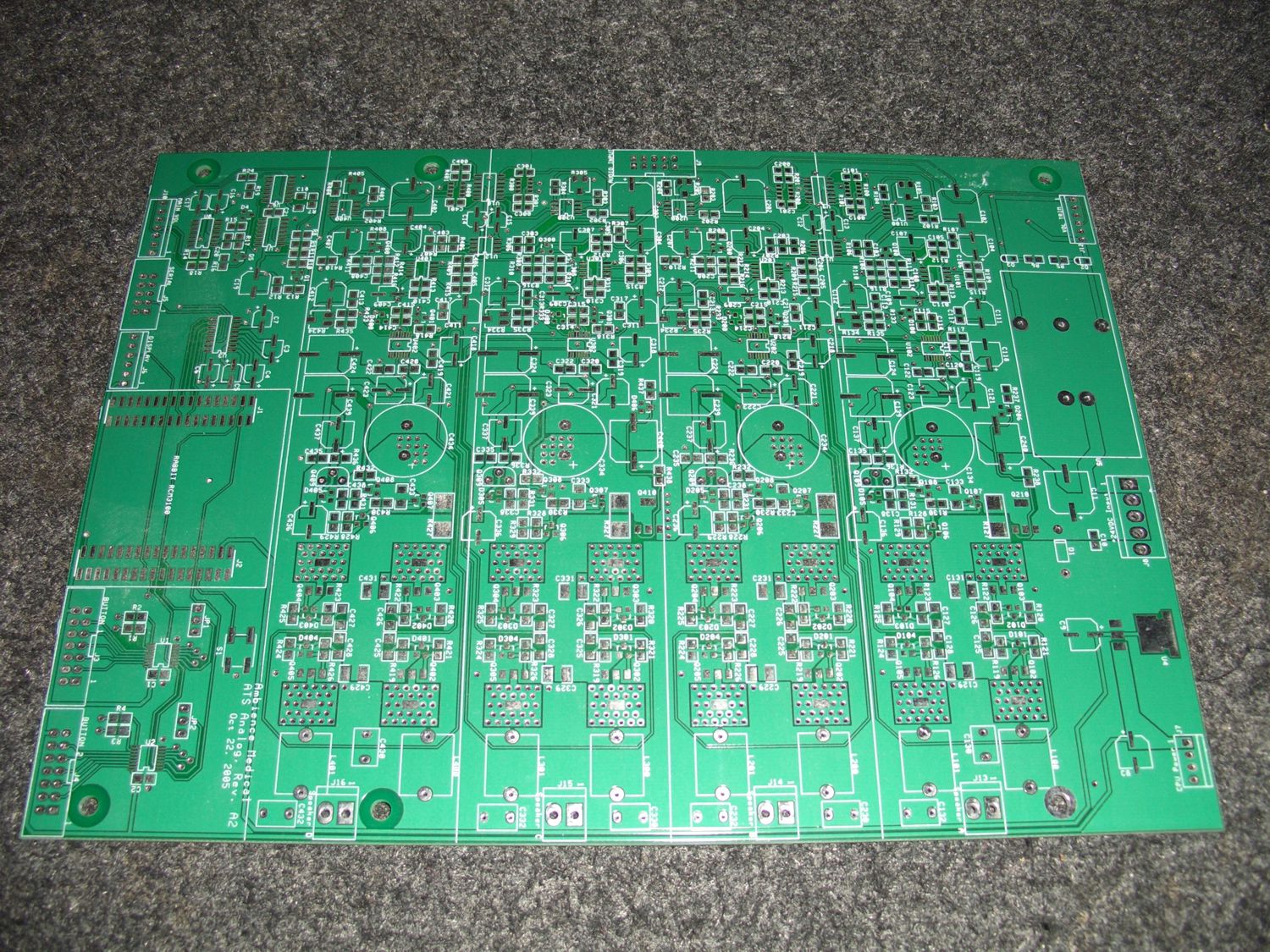
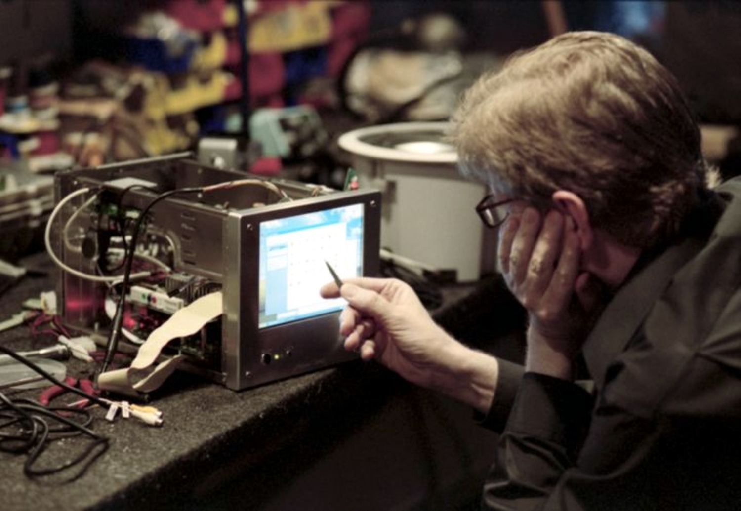
This project started in November of 2004 when Ambience Medical approached us to design an audio media playback unit which could be used in hospitals and healthcare facilities. It was to provide a simple touchscreen interface to operate and provide the user with access to surround sound ambience music programs of nature sounds to assist in helping a patient escape the confines of a sterile hospital environment. The unit consists of a computing platform with a hard drive for storage, a touchscreen display, a four channel audio power amplifier capable of driving a variety of speakers in different hospital installations, a complete power supply and adherence to the safety regulations dictated by hospital safety codes. Additional details about the unit, and the company that installs and supports it can be found on Ambience Medical’s website: |
|
 |
 |
ATS-1 prototype 4-channel audio power amplifier PC board before components have been placed and soldered. |
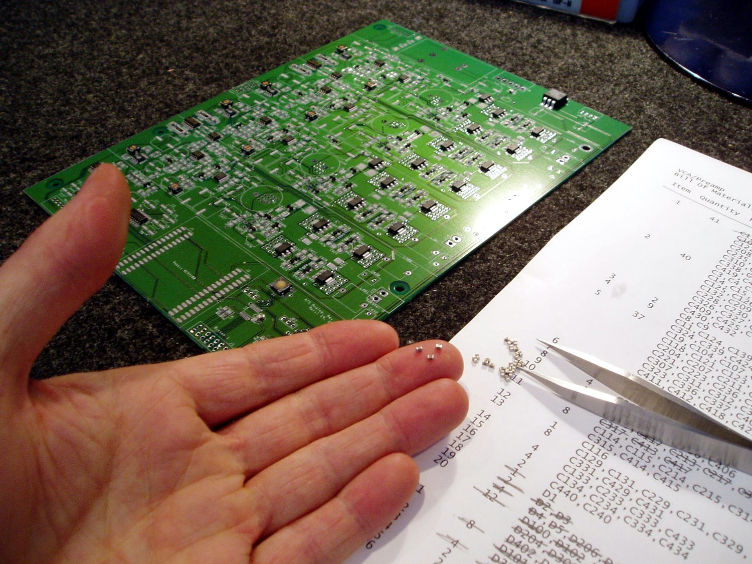
Surface mount capacitors ready to be placed on a prototype ATS-1 4-Channel Power Amplifier board. |
 |
 |
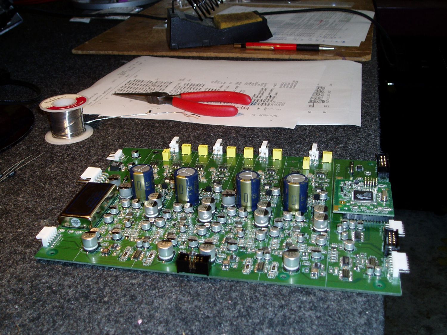
ATS-1 power amplifier fully populated with surface mount and through hole components. |
ATS-1 power amplifier initial power up and testing. |
 |
 |
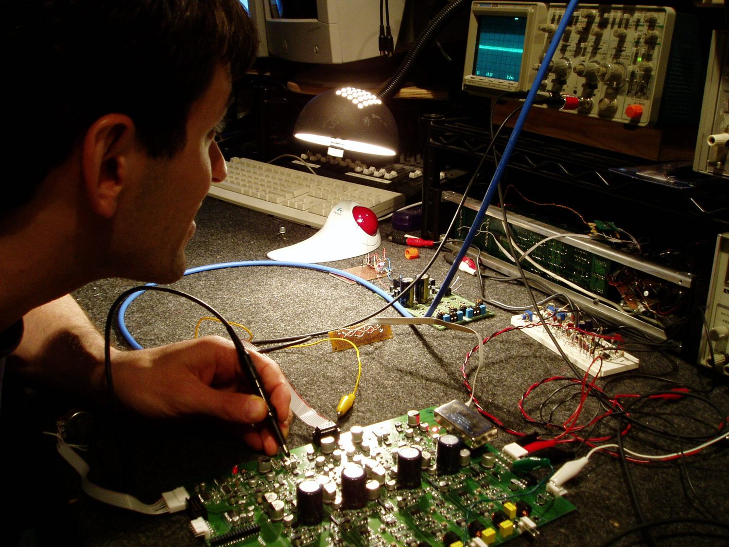
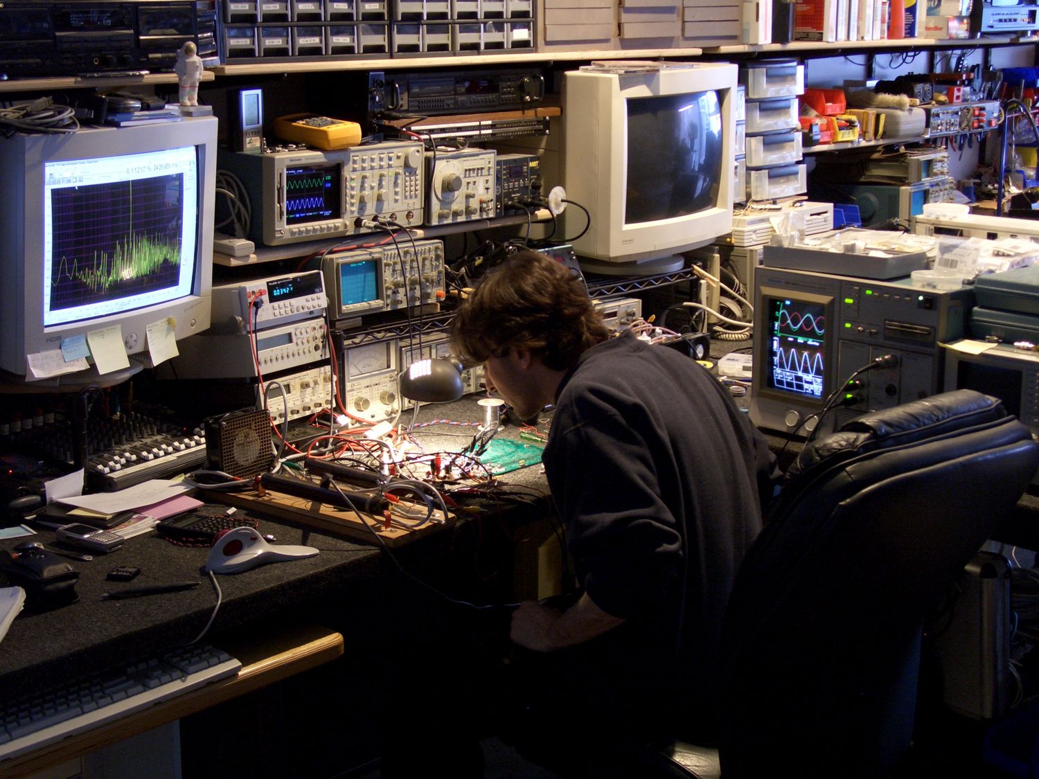
Audio distortion, power dissipation and signal integrity testing with the prototype ATS-1 power amplifier in the research laboratory. |
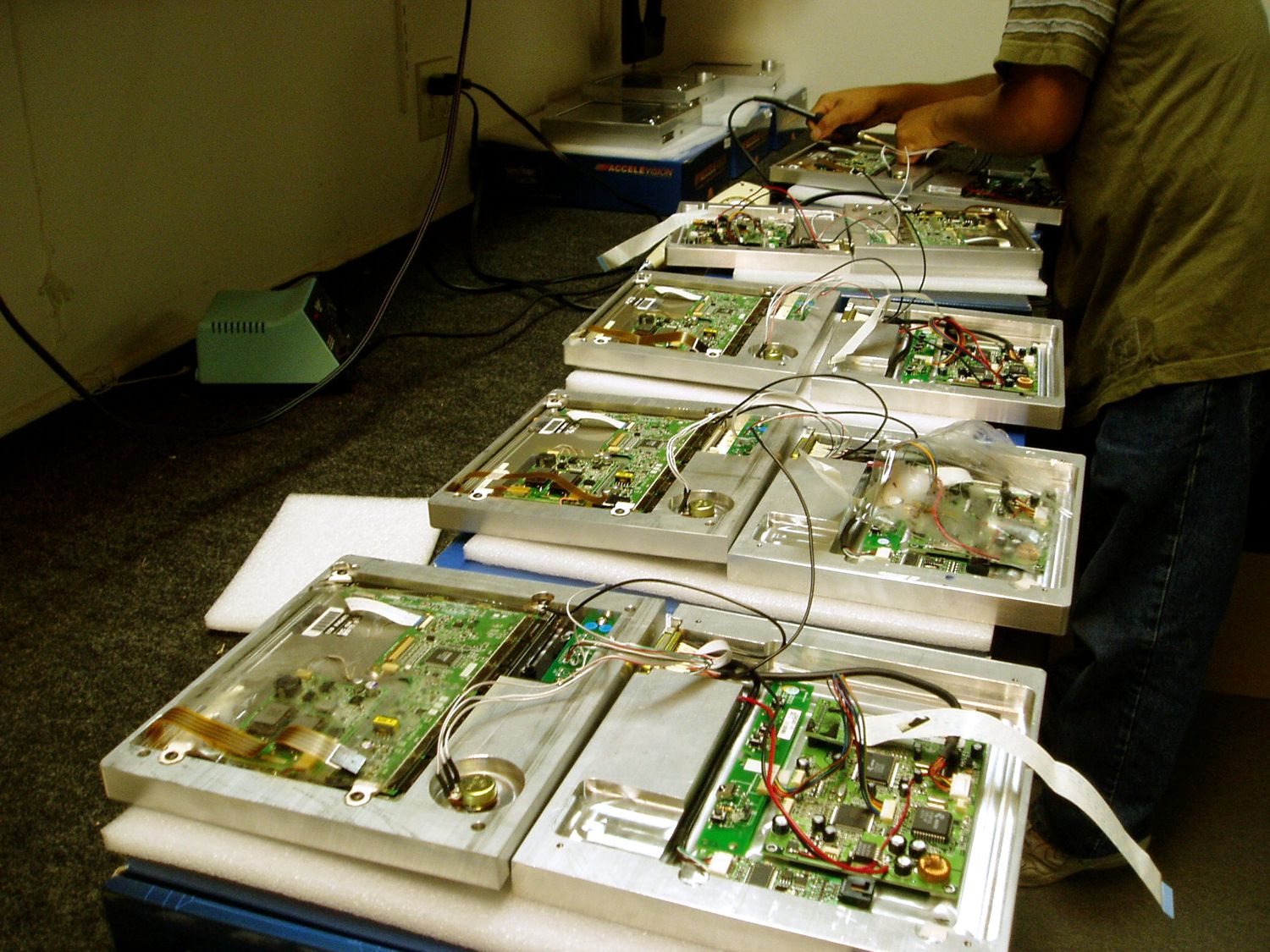
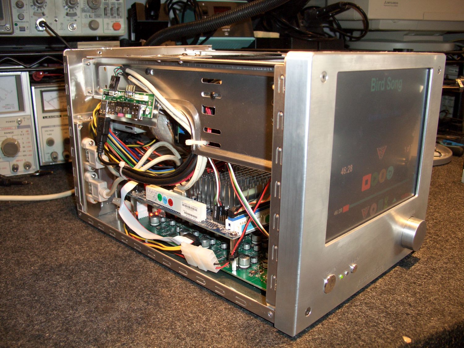
A batch of ATS-1R touchpanel video screens are being assembled with the machined aluminum faceplates and tested prior to attachment to the main ATS chassis. |
 |
 |
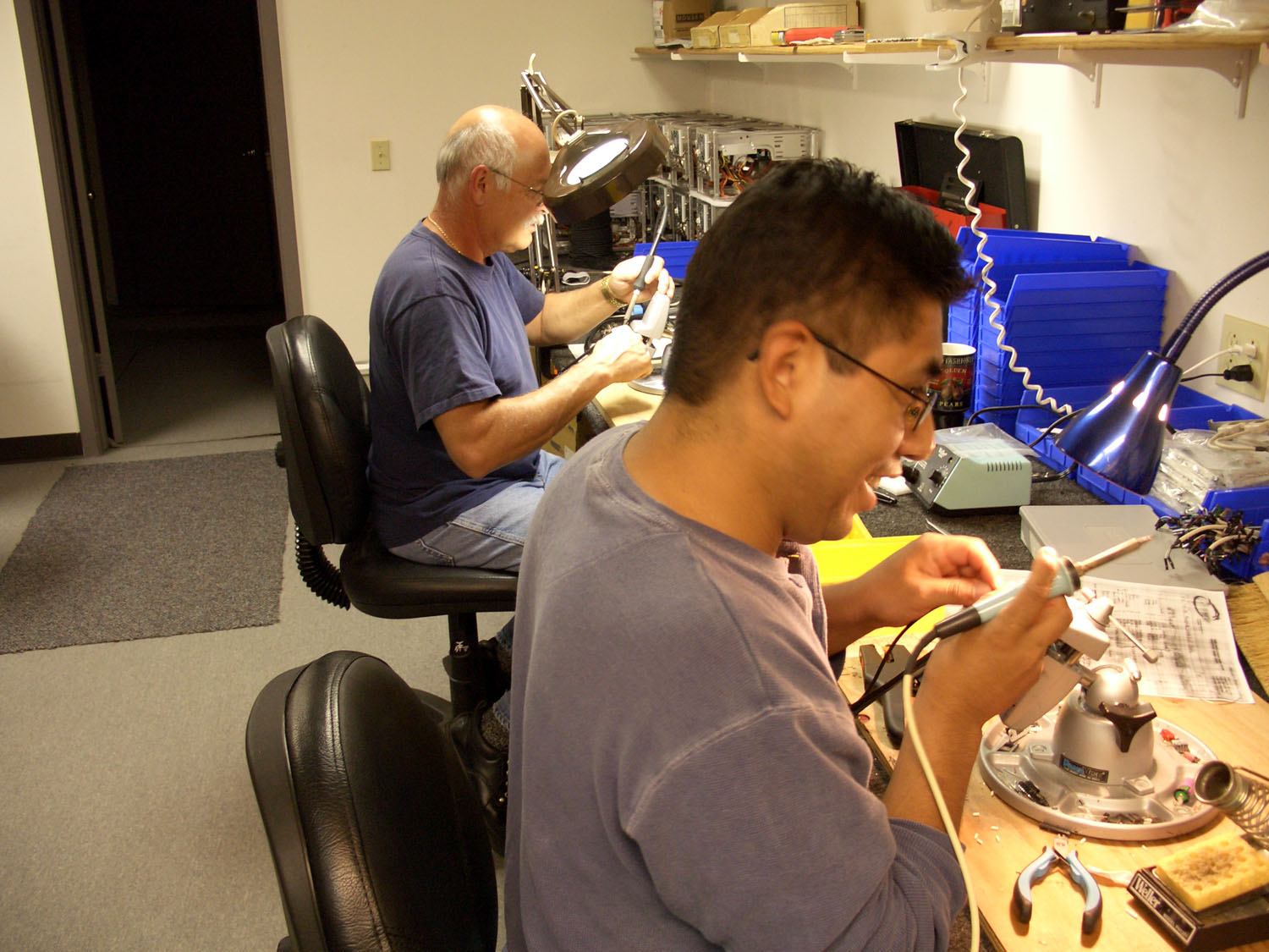
Skip and Susano are busy soldering some of the ATS internal circuitry connections for a batch of units in production. |
Don, our head software engineer is testing some newly added features to the ATS software. |
 |
 |
ATS-1 assembled and ready for preliminary operational testing. |
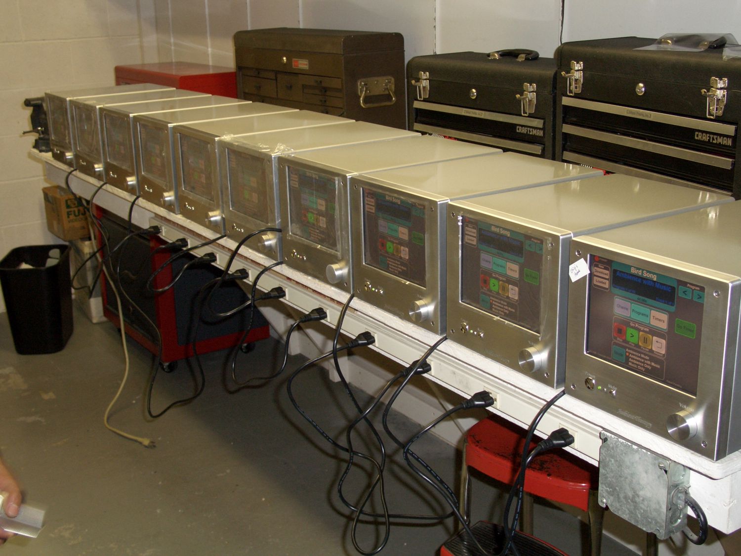
A batch of ATS-1 media players being burned in and readied for delivery to the client. |
|
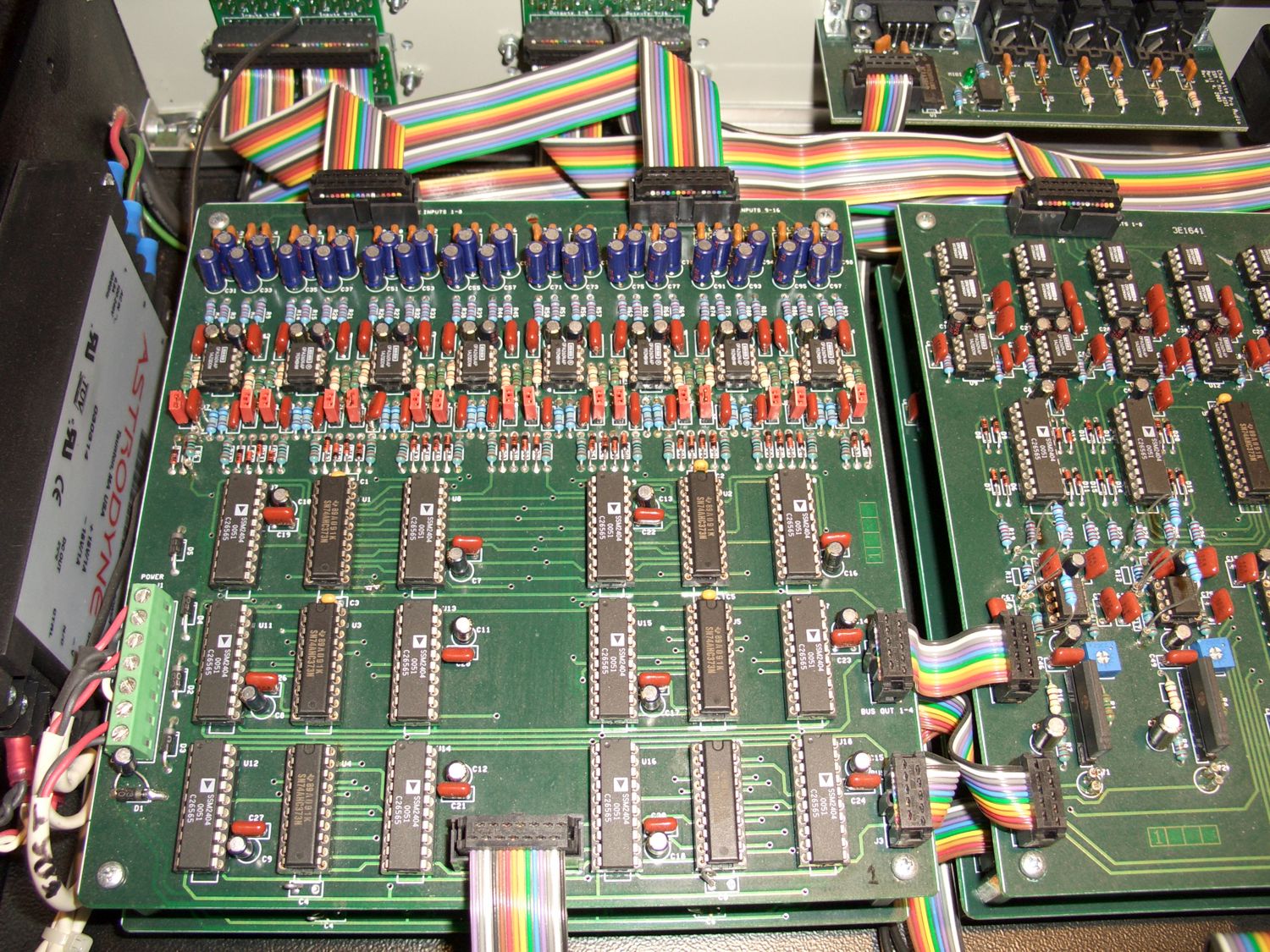
The VAM (Versatile Audio Matrix) is a device that we designed and built to solve a recording studio routing and monitoring problem. The device itself can be thought of as an array of 32 inputs X 32 outputs, each or any of the inputs can be instantly routed to each or any of the outputs and a series of VCAs (Voltage Controlled Amplifiers) are used at the outputs to control the audio gain of the signal passing through the unit. The entire unit was designed to operate from simple MIDI (Musical Instrument Digital Interface) commands. |
|
 |
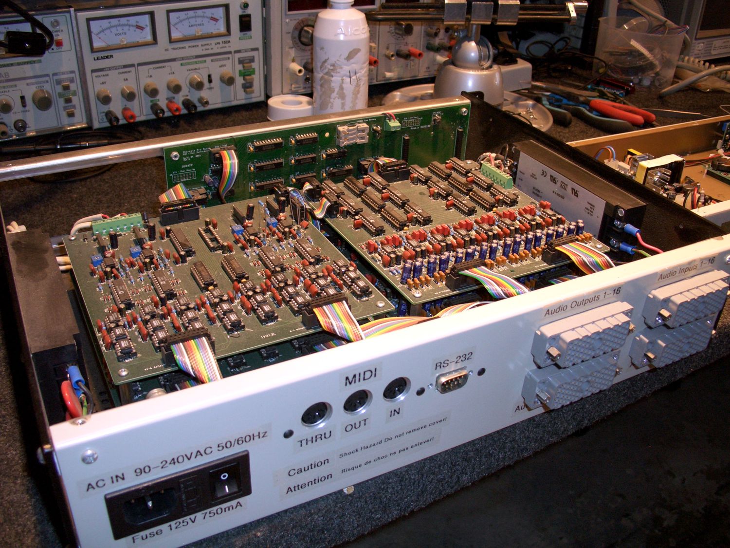 |
A view of one of the two input cards in the VAM. |
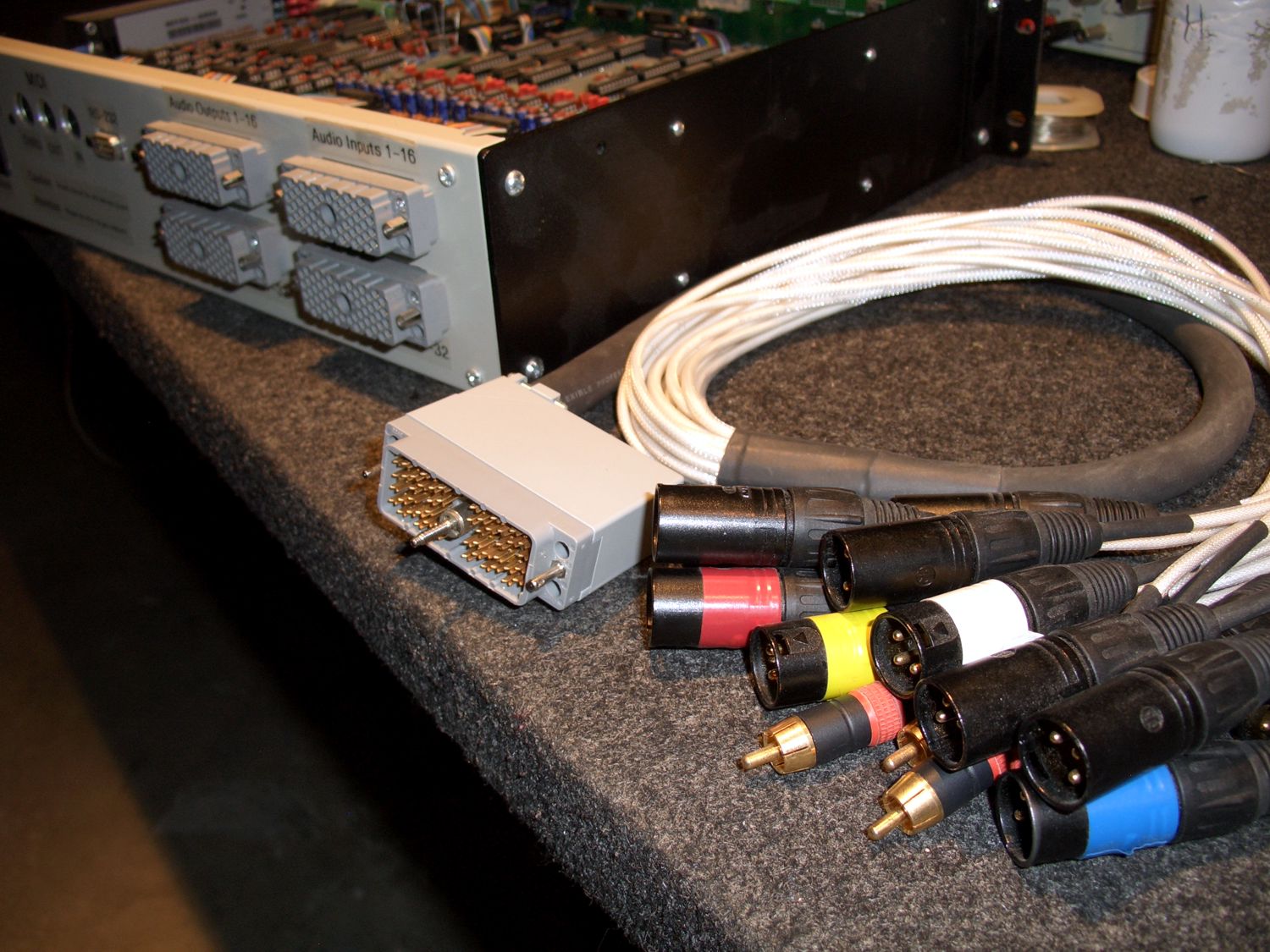
A view of the rear panel showing the, power, MIDI interface and audio multipin connectors. |
 |
 |
A view of one of the VAM’s multi-pin audio interconnect cables. One end of the cable is a 56 pin multipin connector and the other end of the cable has a breakout of several different styles of industry standard audio connectors. |
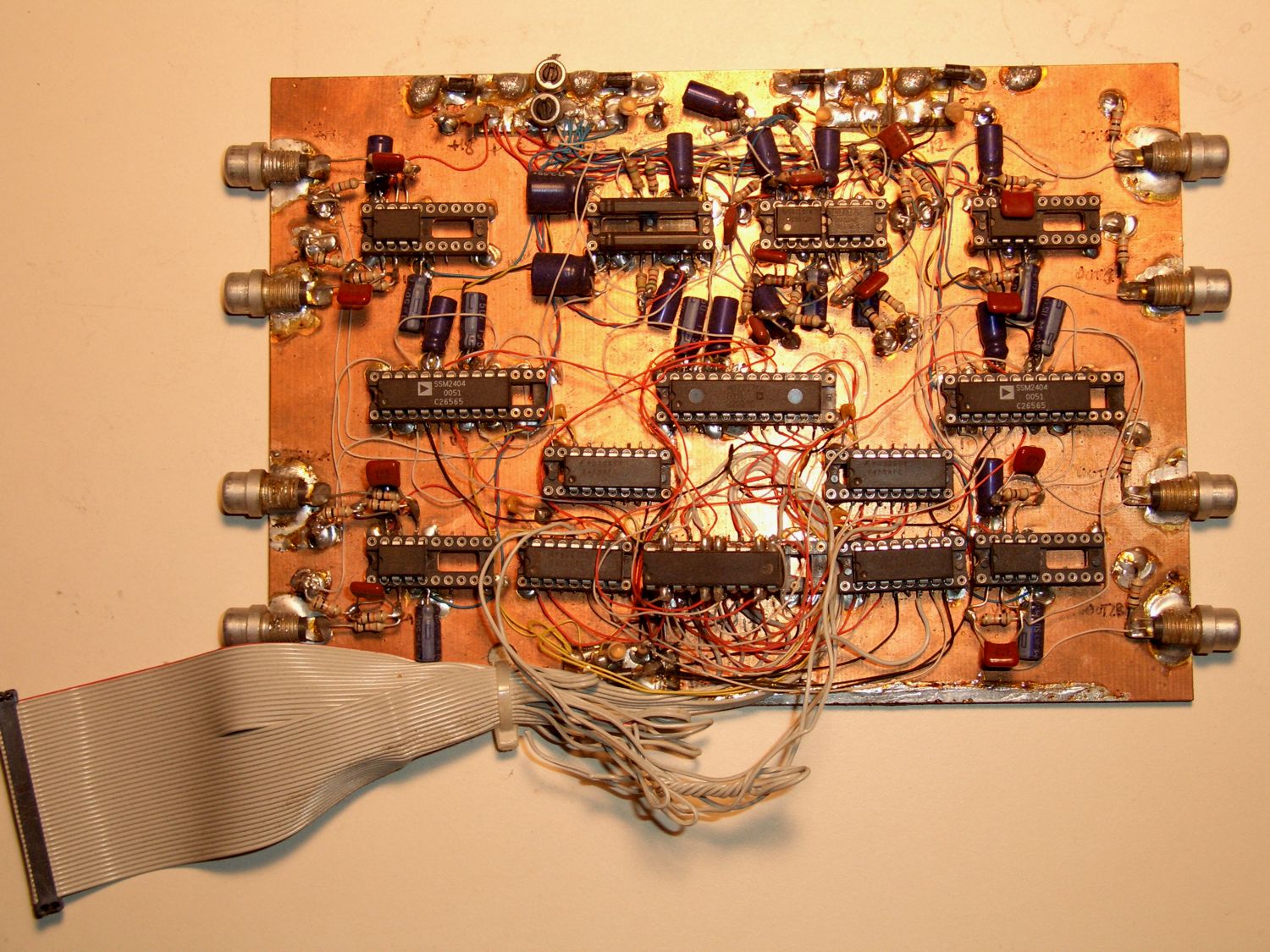
This is the initial VAM prototype board which was used to test the audio signal integrity over two pairs of adjacent lines. Many of the projects are started with rudimentary point to point wiring between circuit components prior to manufacturing PC boards. |
 |
|
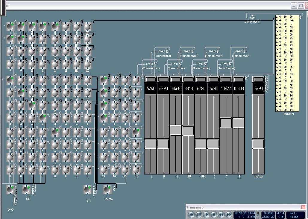
A view of a MIDI control session built in Logic Audio that allows full control of the hardware matrix switches and VCA gains within the VAM. |
|
|
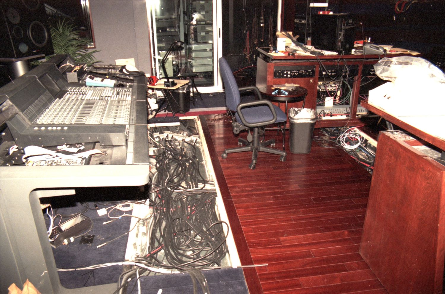
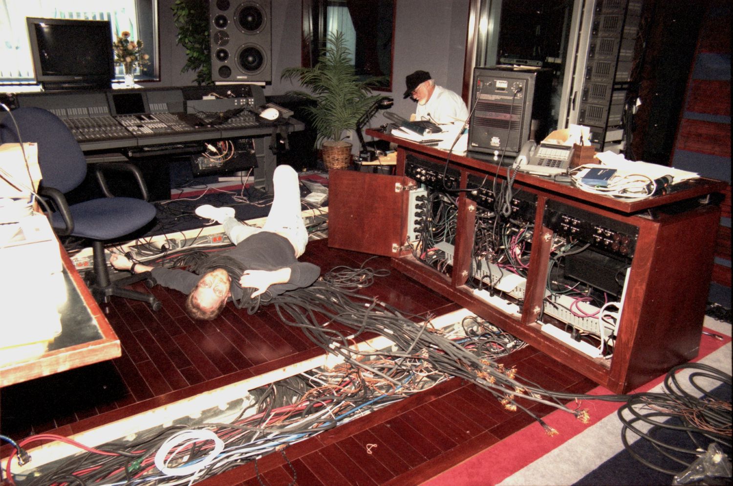
American Gramaphone is a studio and record company in Omaha that is owned by Chip Davis(Mannheim Steamroller). Over the years, the studio has upgraded their gear and implemented a number of installations and customizations. When the studio was first built in the early 90s, the console selected for the helm was the Euphonix CS2000. Subsequentally in the following years, Chip began to really pursue the composition of music in and specifically for surround sound format. So it became necessary to upgrade the console to handle surround sound mixing. Euphonix had a solution in the way of a piece of gear they called the Cube. It's basically a giant 48 X 48 switch matrix with VCAs on the outputs. The unit sidecars to the original tower and a slew of additional cabling was necessary to accommodate the new patchbays and signal runs for the surround speaker arrangement. Together with my collegue Ron and AG's studio engineer Dave, we spent about a month rewiring and installing all the necessary cabling to make the surround sound addition a reality. Once the upgrade was completed, there really wasn't all that much new aesthetically that anyone could see in the control room aside from the new trackball on the console, the 5.1 array of HD-1 monitors, and the additional patchbays in the machine room. Everything new was in the floors and behind the patchbays. Chip would often joke when entertaining guests, point out the Euphonix and say that's the main console and then point to the trackball and say there's our new high tech $50,000 trackball upgrade. After that upgrade, Chip went on to compose and produce a number of his albums up to this day specifically for surround. |
|
 |
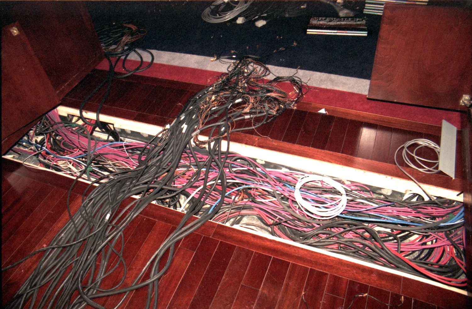 |
All of the cabling from the producer racks and the monitor racks is run in the floors in small tunnel troughs lined with tin. Although it looks like a mess, things are pretty well organized. |
When constructing a studio, one should always remember to budget approximately 1/3 of the expense to cabling. It's always the easy part to forget, especially in a situation where the cabling is hidden so well. Here we see a bunch of runs of Mogami snakes and Apogee AES digital cable. |
 |
 |
A large part of the success of this installation was due to the organizational efforts of Ron who is a stickler for proper documentation and organization. He taught me a lot about keeping things simple, clean and understandable. |
In order to make room for the additional snakes and cabling that we needed to fit in the troughs, we removed some of the original cabling and bundled it with similar new cabling and then laid everything together back into the troughs. |
 |
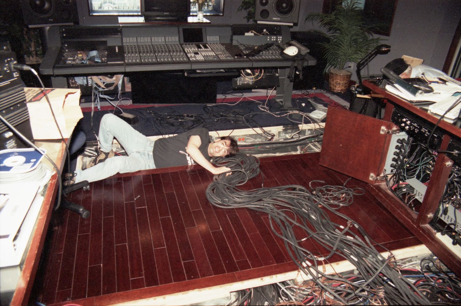 |
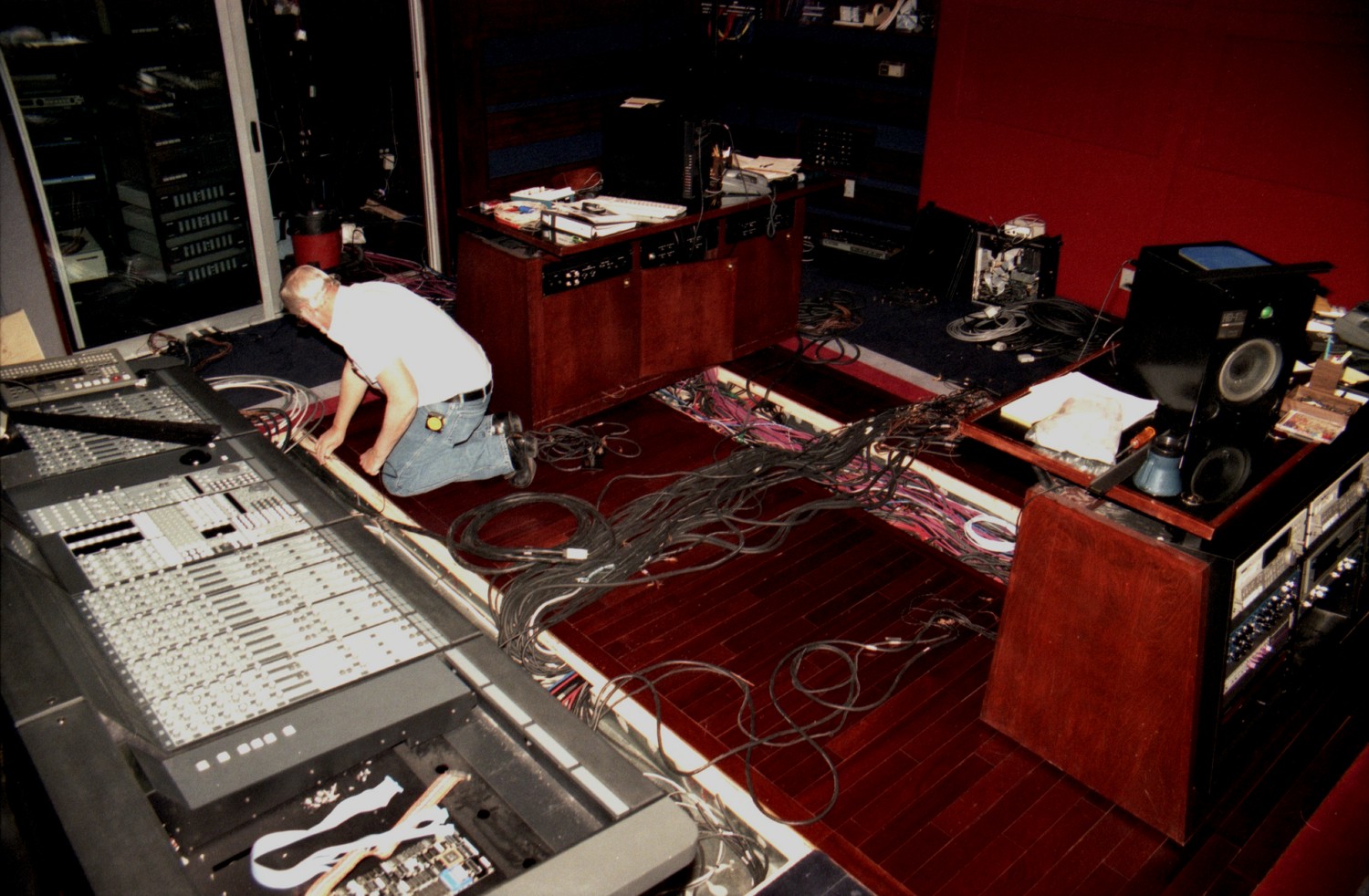
Here's a shot of Dave with Ron in the back. Dave is the studio engineer who assisted with a lot of the grunt work of pulling cabling and plugging everything back into the racks and then testing everything once we were completed. |
Most of the cable pulled pretty easy through the troughs, but we did have our fair share of reaching deeply in there to get a hold of bundles of cable. |
 |
 |
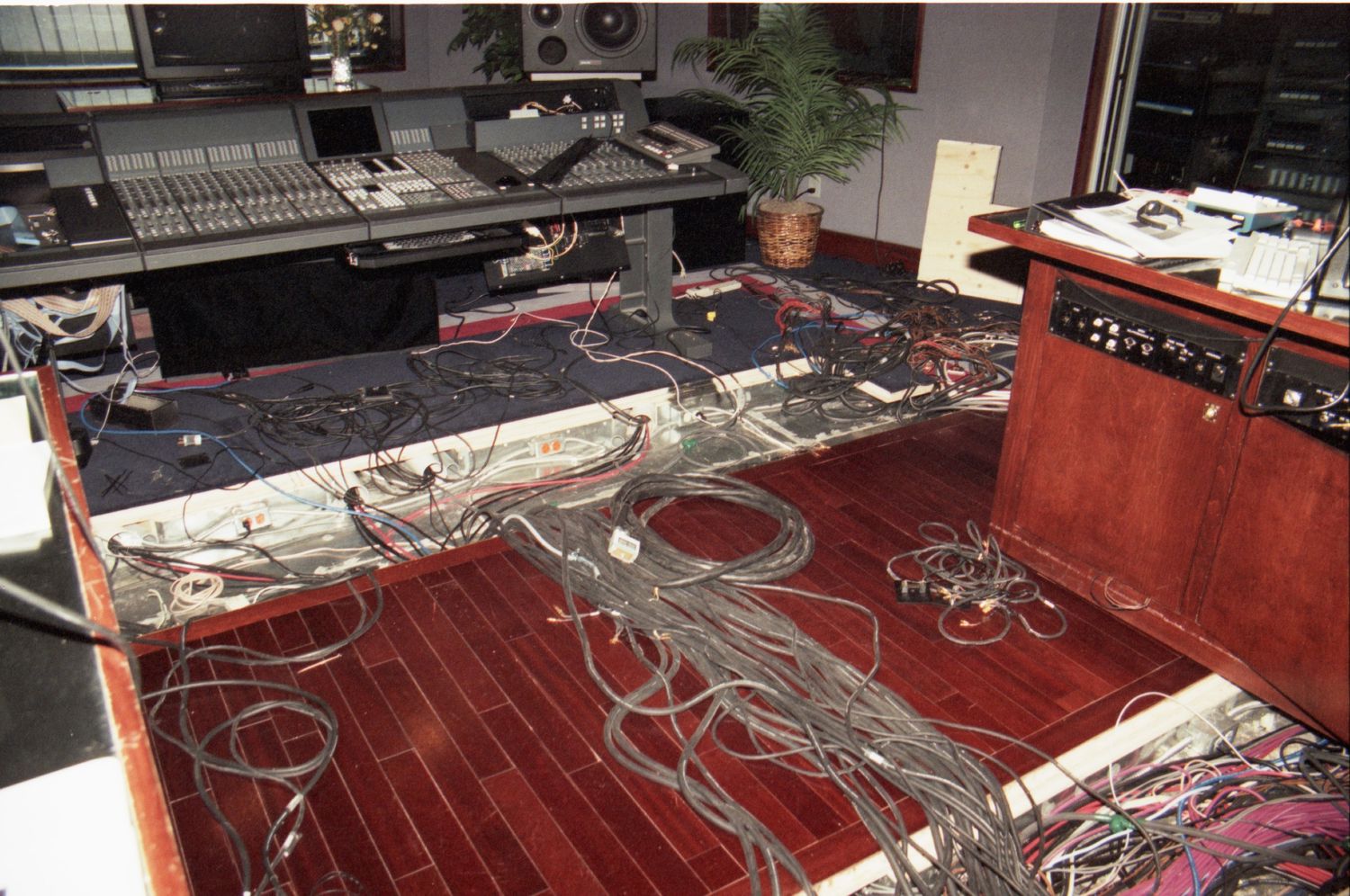
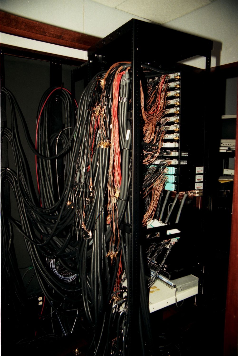
Here's a shot of the back of just one of the two patchbay racks. I bow Ron's task of inserting nearly all of those EDAC/Elco pins himself. These racks are really quite something to pull out as there is so much cable mass on the back of them. |
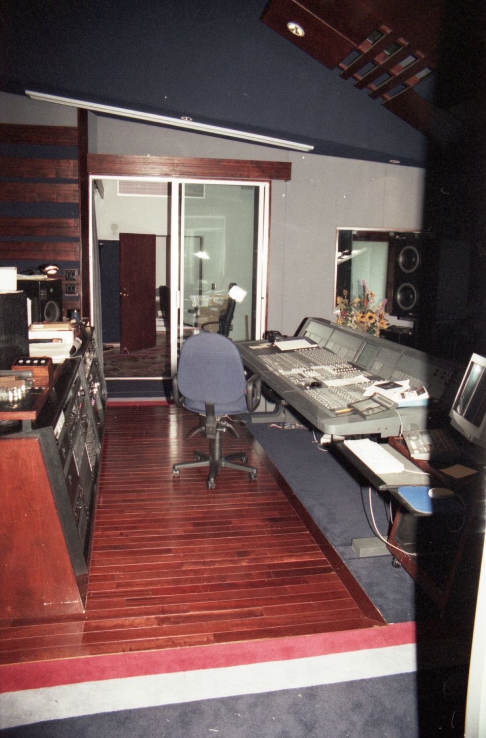
And the finished upgrade, with the new trackball visible on the console surface. |
|
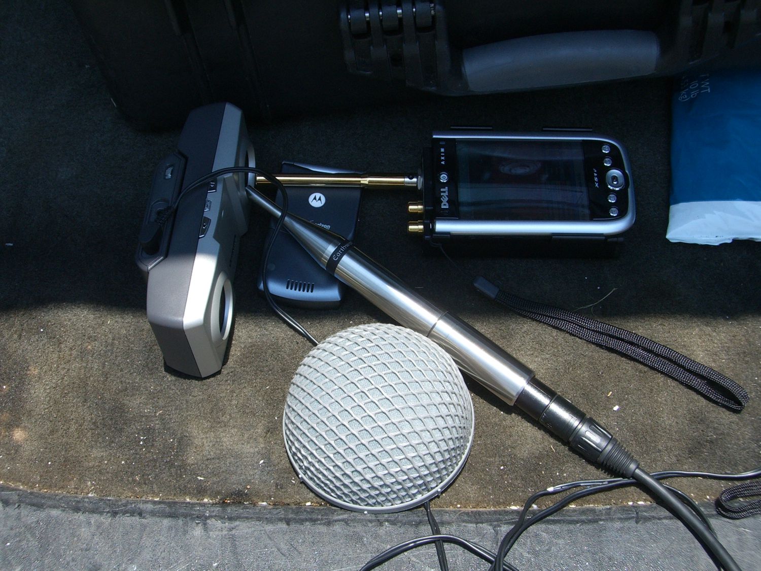
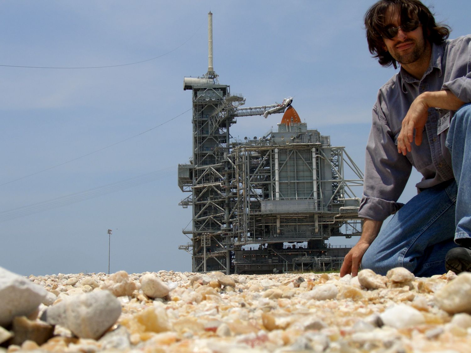
Most recording engineers have dealt with high SPL via a nice screaming Marshall on 11. But what about recording a rocket? A REAL ROCKET. In July of 2006, I was invited by American Gramaphone to assist with a project to record the sound of the space shuttle lauching. And it wouldn't be just stereo, but instead a true surround recording of the lauch. Chip Davis, composer of Mannheim Steamroller has some good friends with some of the Space Foundation personnel and they in turn are connected with the staff of the Kennedy Space Center and and so, due to this relationship, we had some very top notch help and chaperoning once we were at KSC via Scott at the KSC-TV station. We spent a few days figuring out the logistics of accomplishing the physical recording. There are of course many rules and regulations regarding the proximity that one can be to the actual launch pad during the days prior to the launch. Of course, there really aren't too many people, staff or otherwise less that 3 miles away from the pad during the lauch. The project itself on the technical level was a little challenging as the one big question prior to setting anything up was, just how loud are we talking? What kind of mics can we use that will handle the SPL and give us the highest fidelity possible. Well, our answer came in the way of some measurement mics from Earthworks. These mics also allowed us to capture some interesting infrasonic information that can be seen in the spectrum graphs that I've got posted in the library section. If ever you have the chance to witness a launch of a rocket of this size, especially one carrying people, don't hesitate to jump at the chance to see it in person as it really is a spectacular moment to remember. |
|
 |
 |
We set up our mics and preamp gains using a known SPL noise source. We did a series of calculations on the noise generated from previous launches to determine the approximate levels that would be corresponding to the locations where we had the mics set. Then, we figured in a headroom of 20dB on top to insure we didn't clip in this "ONE TAKE" event. |
We had a few small issues from time to time with some cabling noise and it was necessary to investigate the gremlins and use our cell phones for communication since the radio traffic on KSC is highly controlled. |
 |
 |
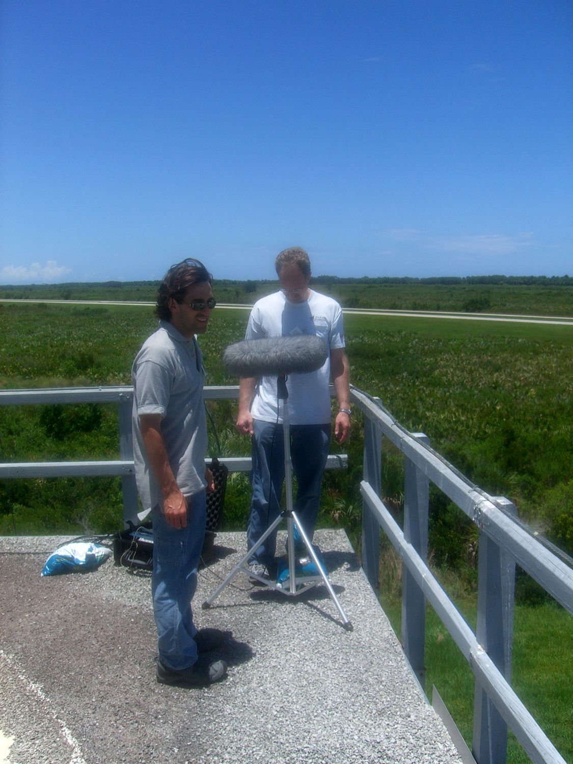
Dave and myself are at a weather station just east of the shuttle landing runway setting up one of the recording locations. |
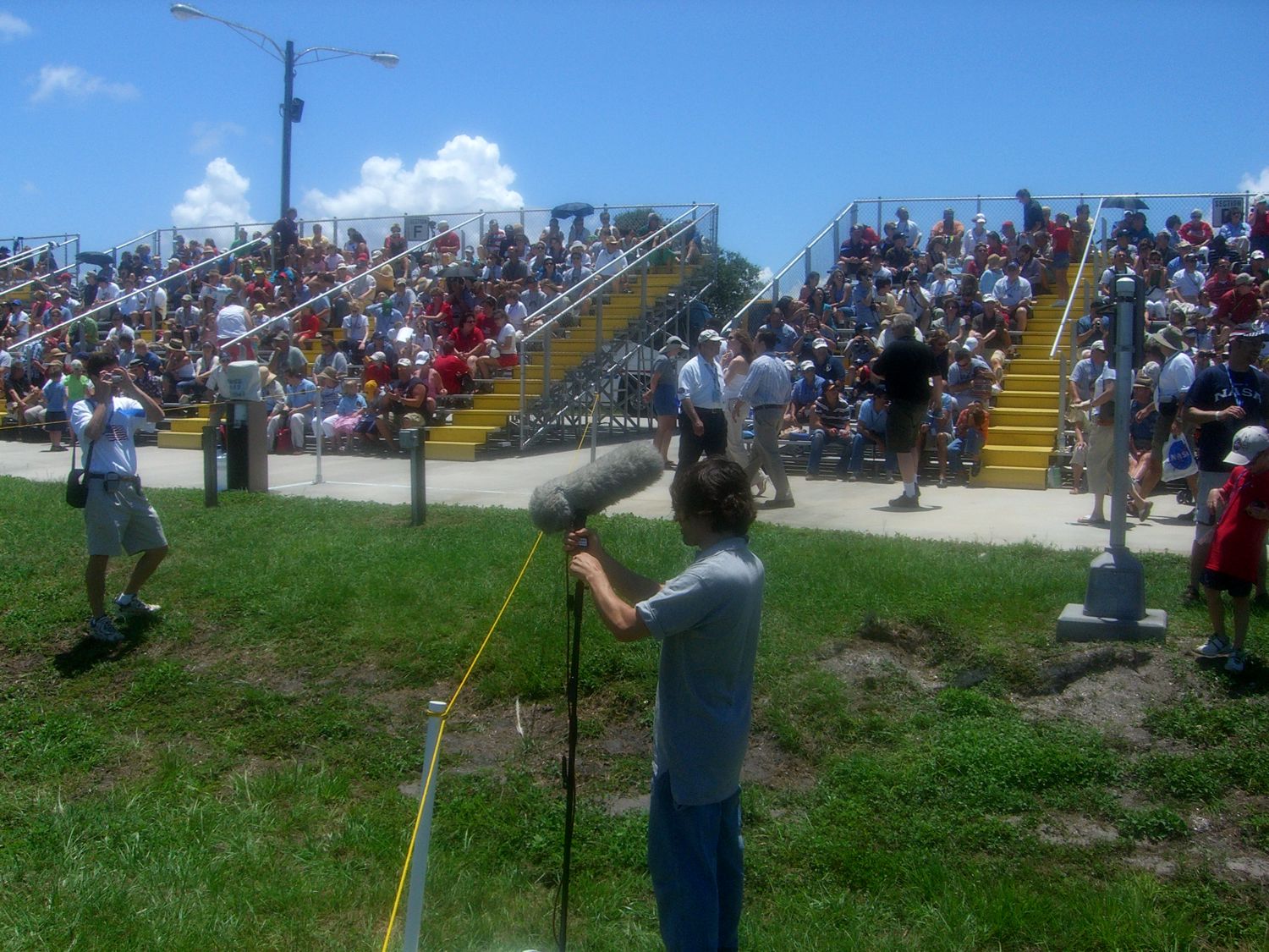
Another additional element to the recording was to get some audience applause and cheering from the VIP seating area. This location is roughly 3 miles(5km) away from pad 39-B where the space shuttle Discovery was being launched from. |
 |
 |
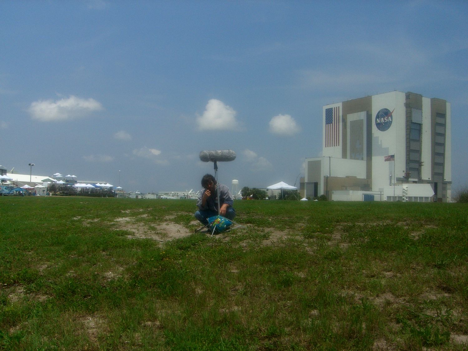
One of the joys of this adventure was getting right up close and personel with all the hardware. Discovery is just behind me here on pad 39-B. These rocks in the foreground are changed every so often as when the shuttle on the crawler rolls over them, over time, they're crushed by the sheer weight and eventually turned into sand. |
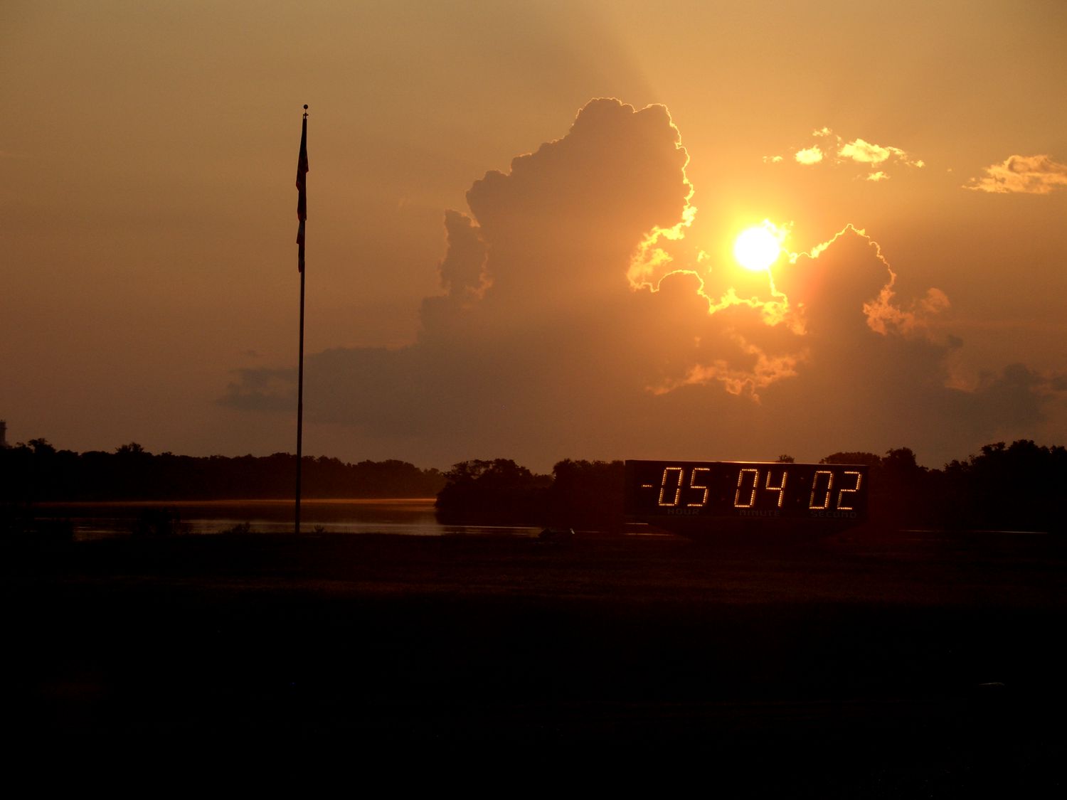
On the morning of July 4th, 2006, it seemed we had a fantasic day day for a launch that already had been scrubbed twice prior to this third attempt. And, as this beautiful morning predicted, the space shuttle Discovery, STS-121 lifted off and we proudly recorded her guitar riff on 11. |
 |
 |
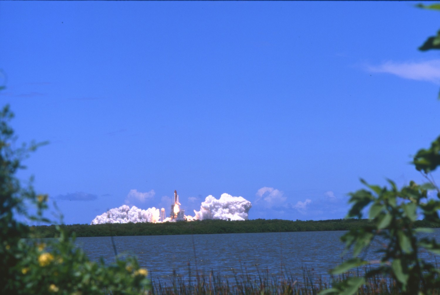
T +0:00:04 |
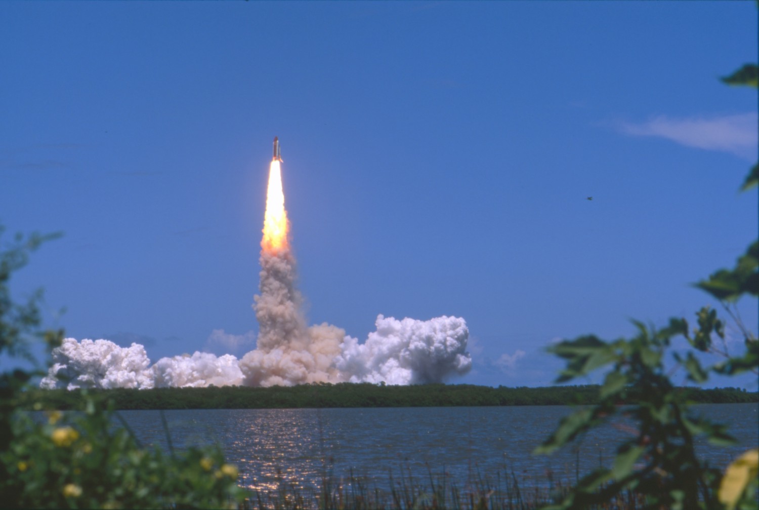
T +0:00:09 Go baby GO! |
|
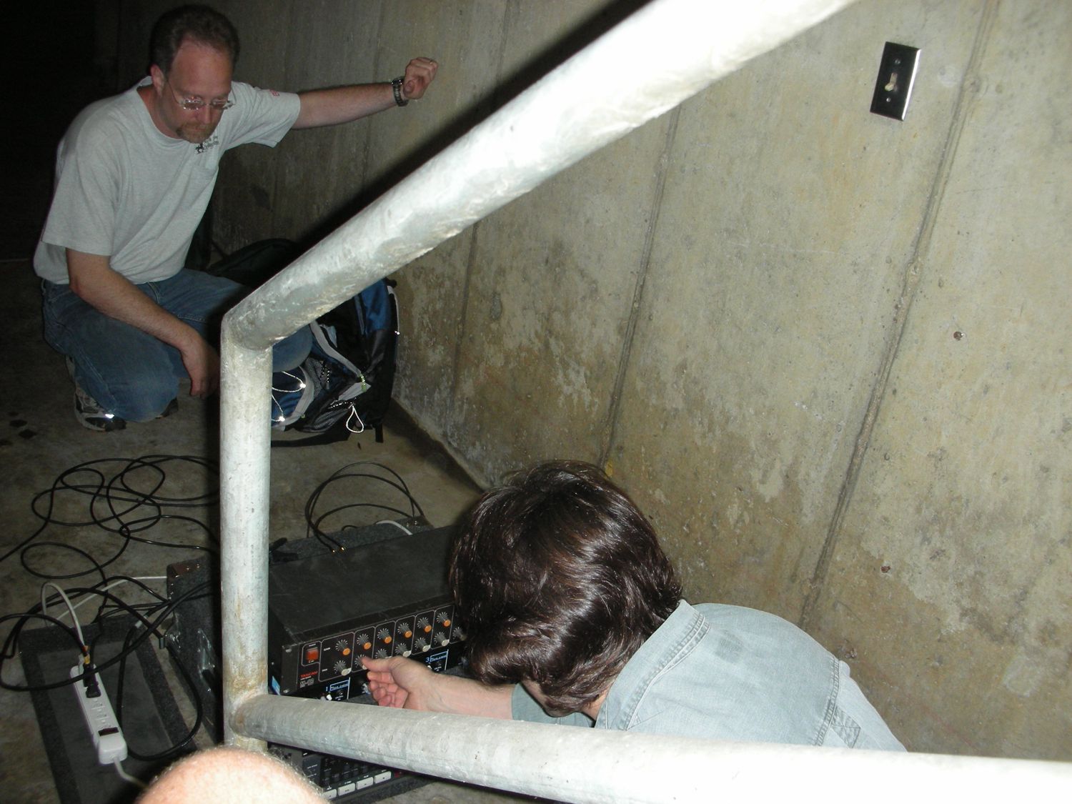
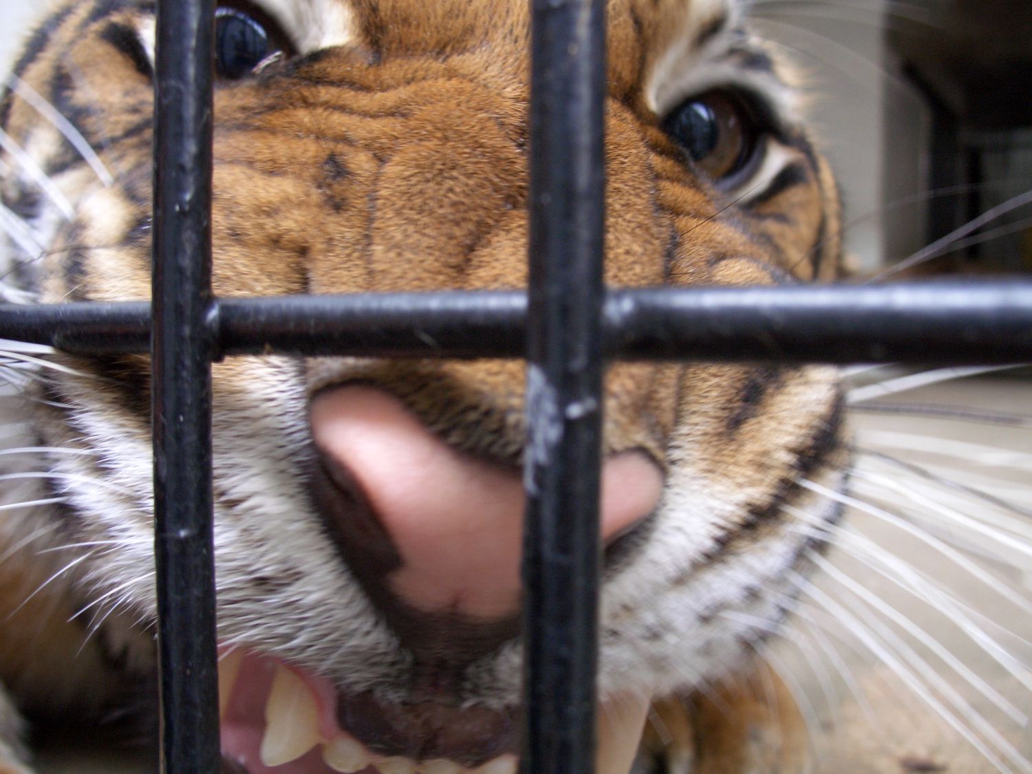
Another interesting recording project that we found ourselves involved in was an opportunity to work with tigers. A local hearing research doctor had been studying the communication patterns of tigers. He theorized that they communicated to one another in the wild with vocalizations that would be partially sub-sonic to human hearing. He had asked American Gramaphone and Chip to come out and see what kind of recording could be done to capture the sounds these majestic creatures were making. They in turn invited me out to assist with some of the technical aspects of the project. I must say, it was quite an opportunity to get up close and personal with these big cats. We had recorded a tiger that was kept out of public view due to its personality as it was a tiger that had come to the zoo from an abusive past in a circus and wasn't very happy about life in general. Anytime that someone would approach his cage, he would growl in a way that instilled an obscene sense of deathly fear in just about anyone and anything in the close proximity. I had SPL/RTA meter in my hand(attempting to hold it steady) and was measuring 130db(SPL) at times from a distance of about 5 meters from this animal when he would let out a very aggressive growl. Impressive lungs to say the least. |
|
 |
 |
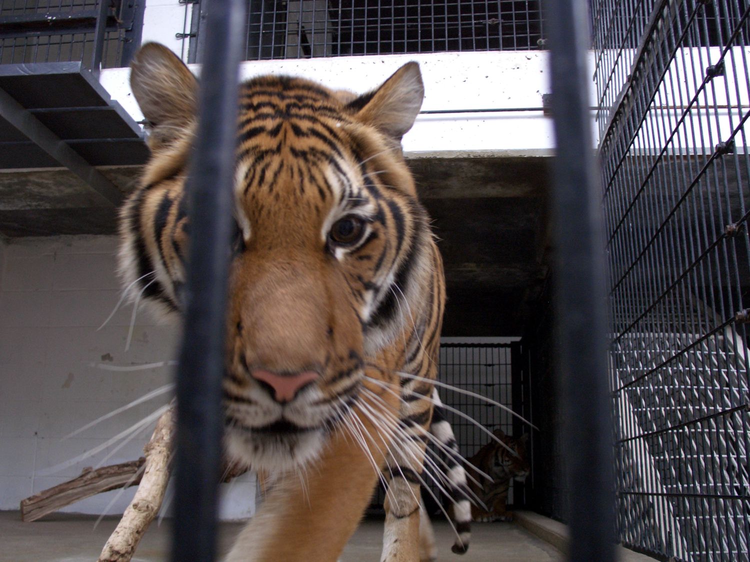
The first room we recorded in, was the tiger that didn't like anyone around as explained above. We tried our best to get the recordings as quick as we could so as not to irritate him anymore than necessary. |
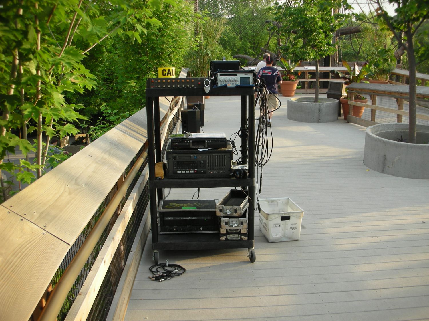
We used the Earthworks measurement mics along with a Diva recorder to see if we could register some of the LF energy the tigers used in their vocalizations to one another. |
 |
 |
We spent a little time with some tiger cubs who were more than curious about our presence. These guys weren't too vocal, but it was still enjoyable being so close to them. |
This cub in particular was very interested in everyone and kept coming right up to the front of the cage to sniff out whatever. |
 |
 |
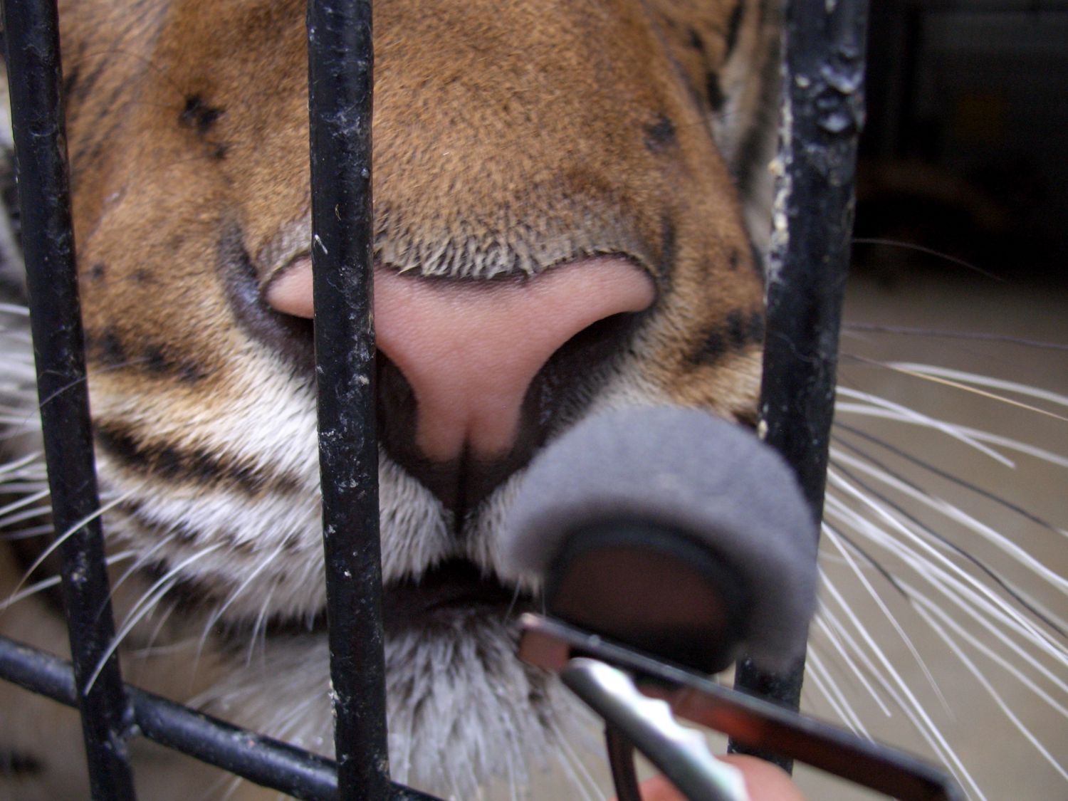
Although it appears he is ferociously preparing to attack, he was really just scrunching up his noise and really sniffing carefully. |
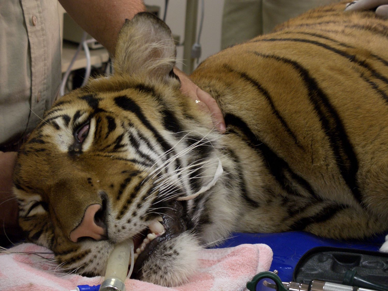
This tiger is under sedation and was needing some dental work. While he was under, he was given some hearing and nerve impulse processing tests on the nerves in his ear canel. |
|
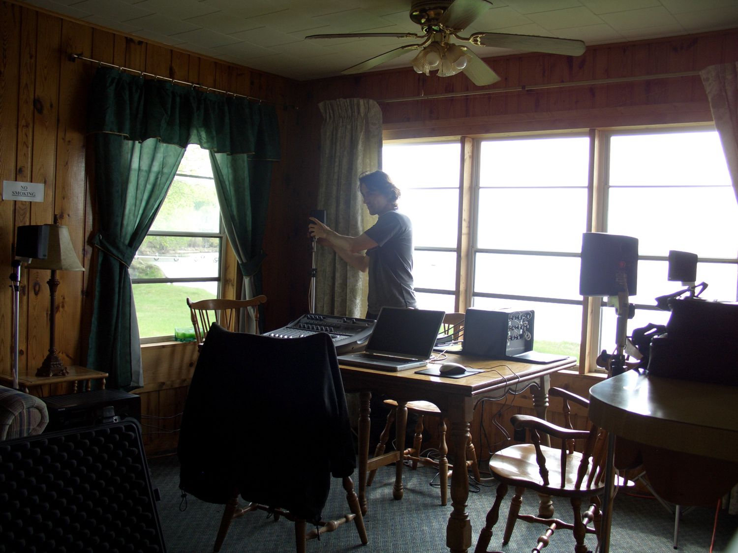
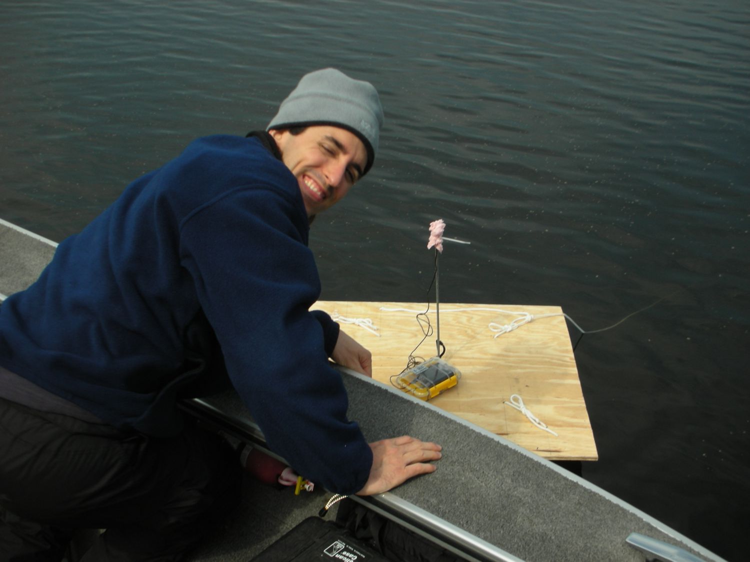
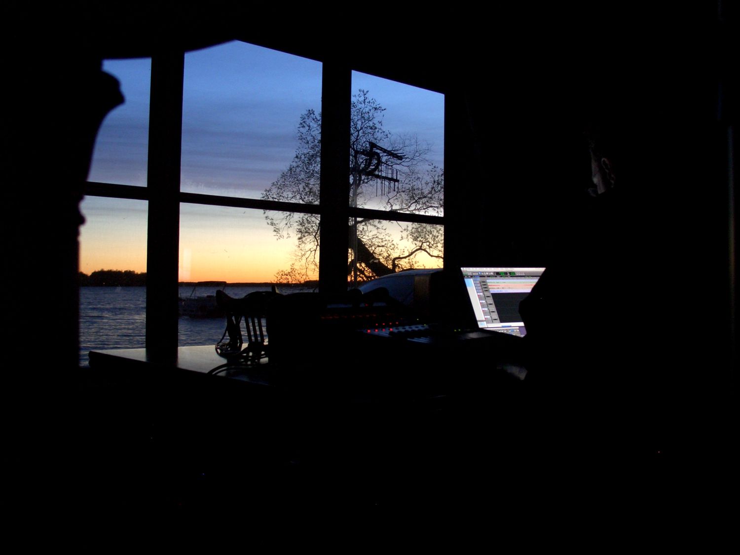
The ATS Ambience playback unit from above has in it several surround recordings of nature and music composed specifically for those environments by Chip. One of the ambience recordings that we tackled was the sounds of a lake in Minnesota with the wonderful distinct sounds of the loon. We set off with some ideas from the technical side of it to accomplish some things that Chip had in mind. One of the more notable experiments was the placement of microphones on the water surface. We used some tractor inner tubes with a rod running vertical and then a small windscreen and omni mic with some high fidelity Lectrosonics wireless transmitters. The result was rather interesting when we had a calm lake and any sound of a bird flying around bounced off the water and made for a really unique ambience quality in and of itself. |
|
 |
 |
We set up a PTools LE system with a small surround sound monitor arrangment so that we could actually monitor in surround while the recording was taking place. |
We set up microphones on the water to try an experiment to see what kind of ambience would come about with the reflections off the water. |
 |
 |
At night, the peeper frogs really got going quite loud. The ambience that we could hear, really put you at the surface of the water. |
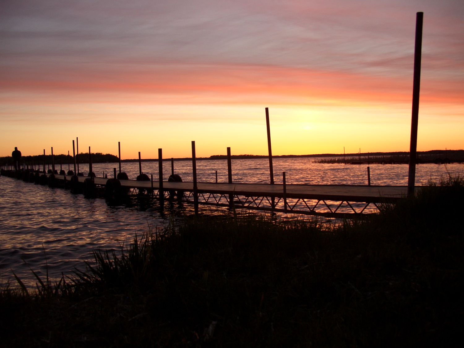
The ambience recordings really do a great job of helping you to imagine the landscape that was the lake we recorded at. When hearing those recordings, I'm reminded of the scenery above. |
|
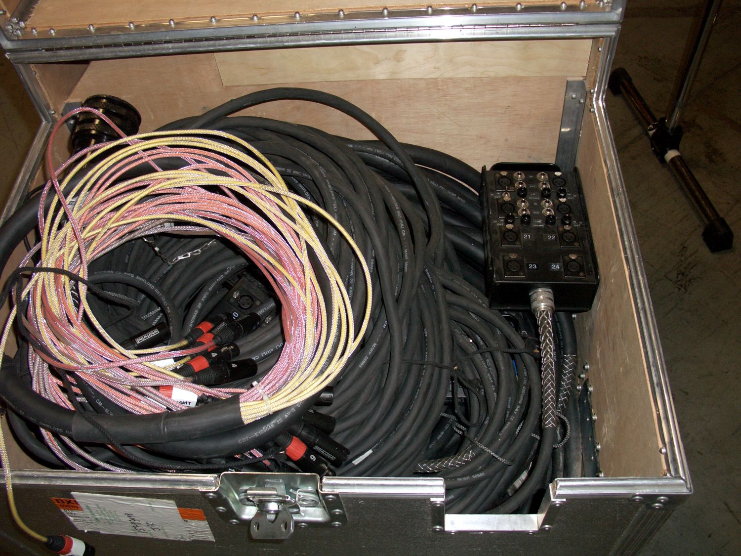
A local concert touring company frequently has appearances in television studios where they need to interface band sound equipment into the TV station equipment. We designed and built a custom 24 channel microphone isolation splitter to handle this task. The project demanded several multichannel snakes with multichannel connectors to quickly be able to setup and tear down the interfacing of a live band to a television studio for broadcasting purposes. The entire system is passive and self contained in its own rugged road case. |
|
 |
 |
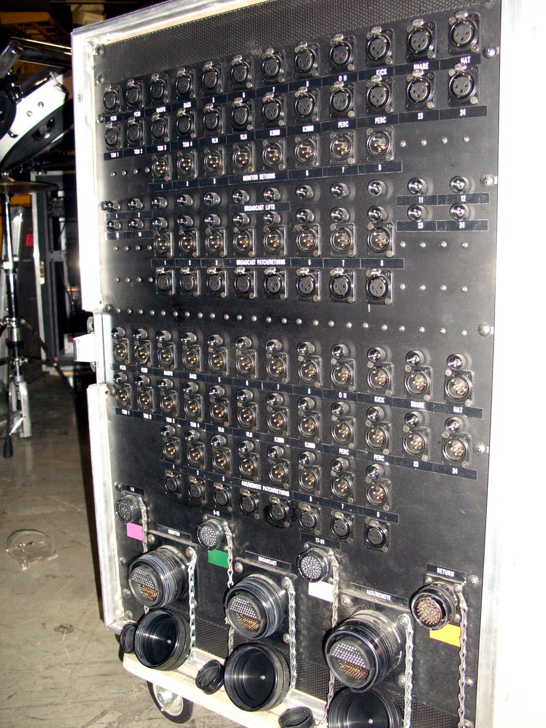
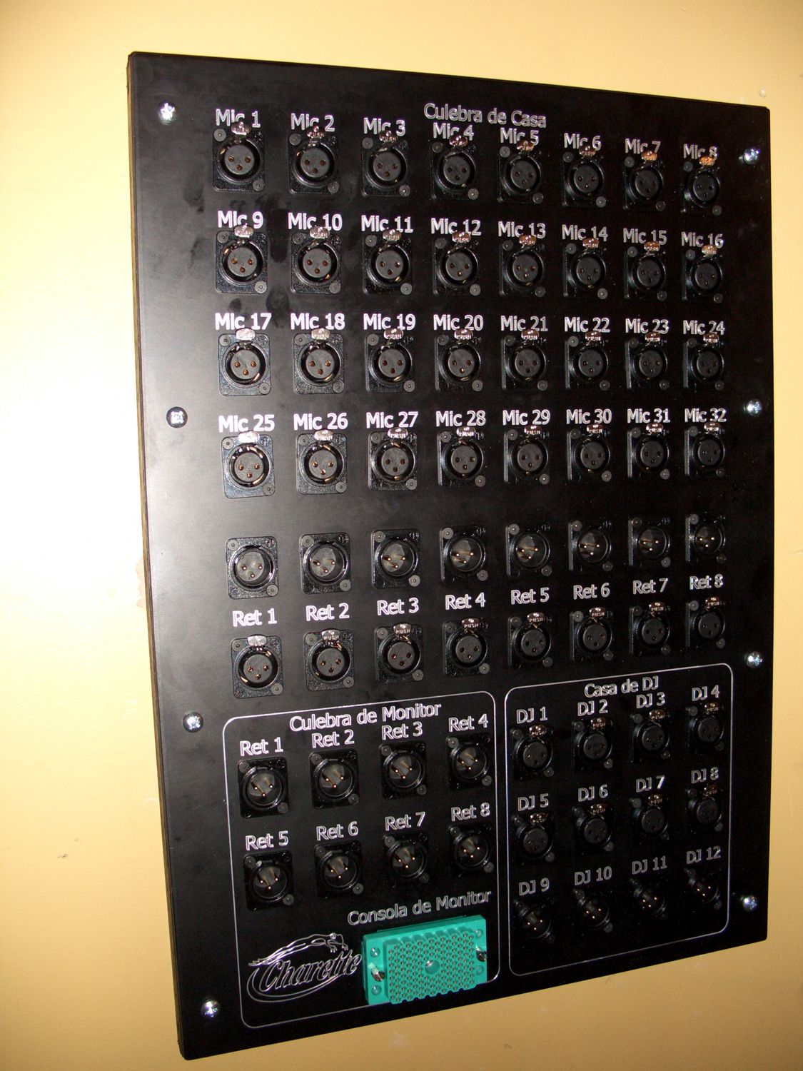
This is the front panel to the microphone splitter. The panel is integrated into a ruggedized road case for transport. The system is a 24 channel input with 8 channels of returns. Two of the three sets of inputs are truly transformer isolated and provide complete isolation for the broadcast and recording feeds. |
There are several multipin breakout cables and multichannel snakes which allow the splitter to interface into a variety of situations over several hundred meters of distance. Each audio input and output are clearly labeled for easy identification. |
 |
 |
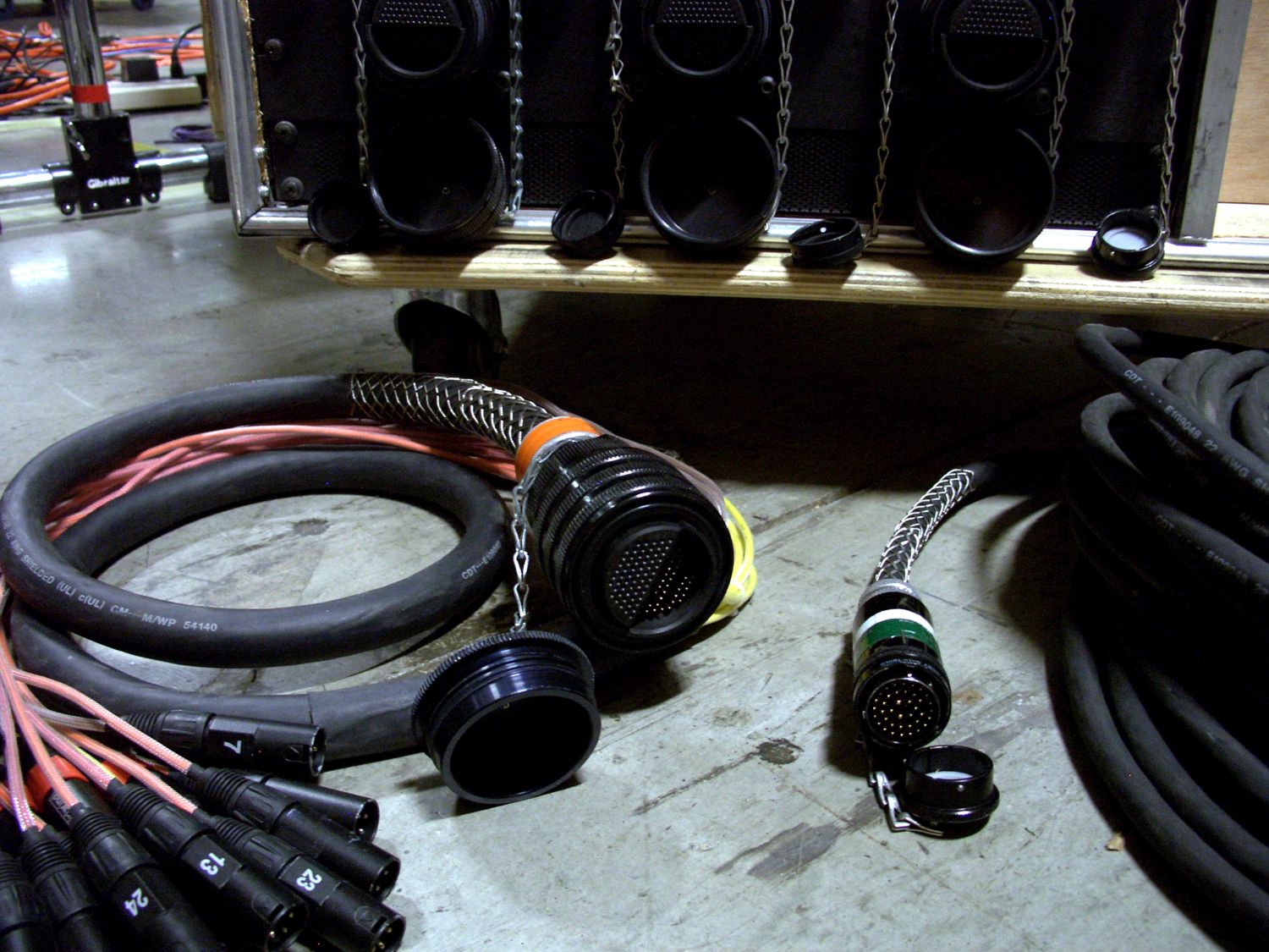
This is a view down into the rear of the road case where there is the compartment for storing all of the interface cabling and multichannel snakes. |
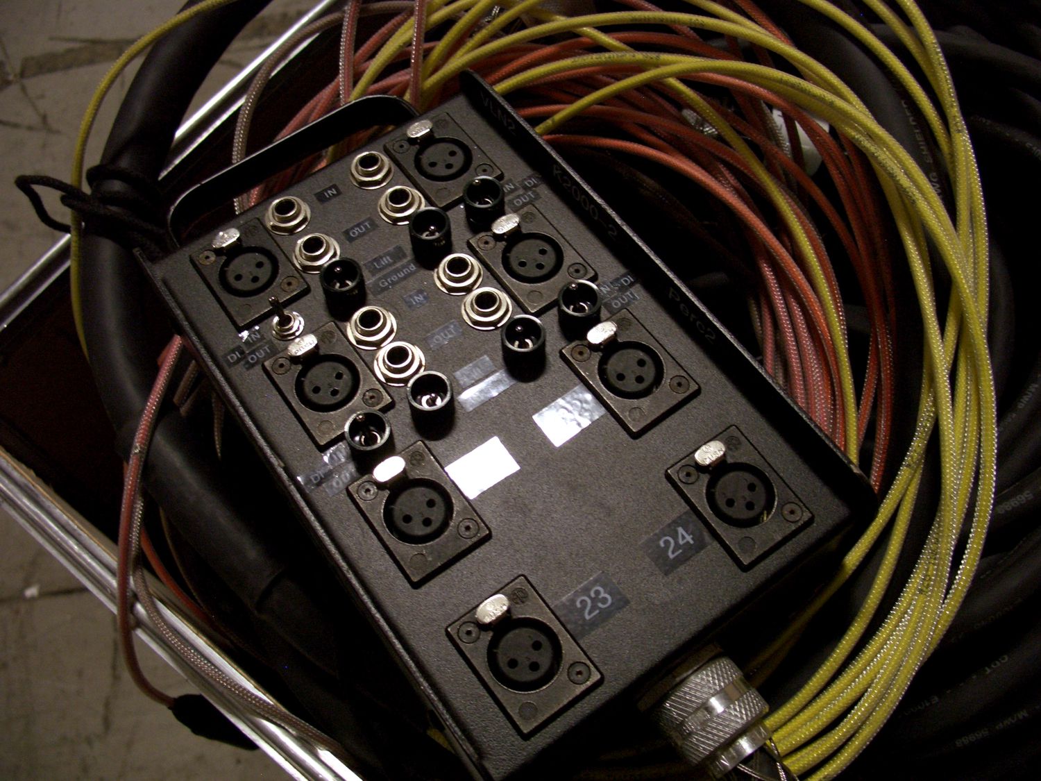
A close up view of one of the snake heads that provides transformer isolated instrument inputs as well as microphone inputs. |
|
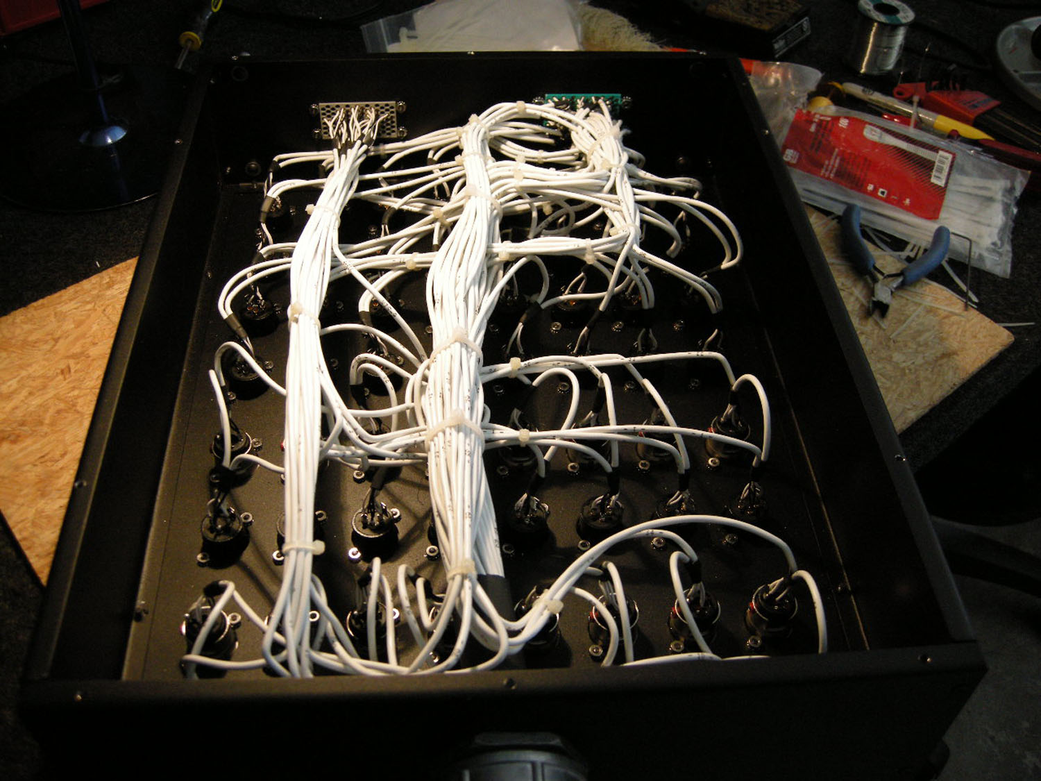
Typically, we're asked to put together a compact and portable type of snake system to accommodate bands and their equipment when playing in different clubs and venues. The following pictures show a typical portable snake design that was designed and built with multipin connectors to facilitate quick hookup and disconnect. Aside from the main feed to a house console, it also includes a parallel split which allows for anything connected to the stage snake head to feed a second position such as that for either a monitor console or a recording setup. |
|
 |
 |
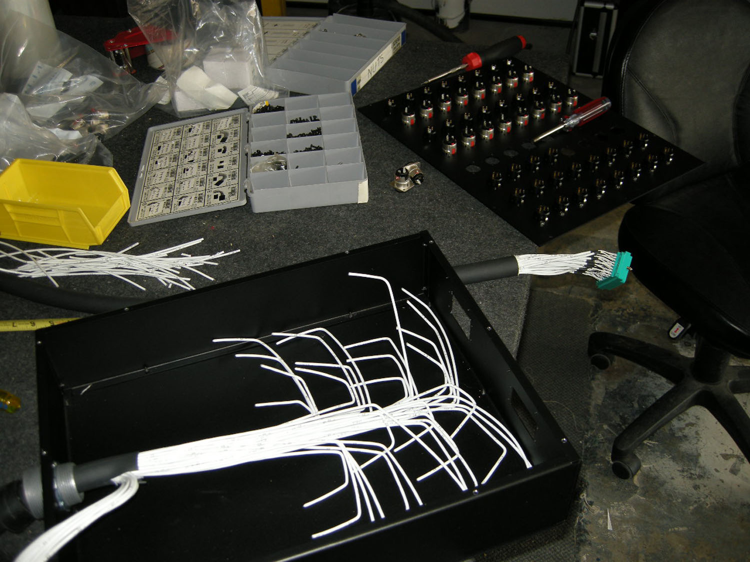
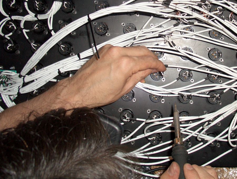
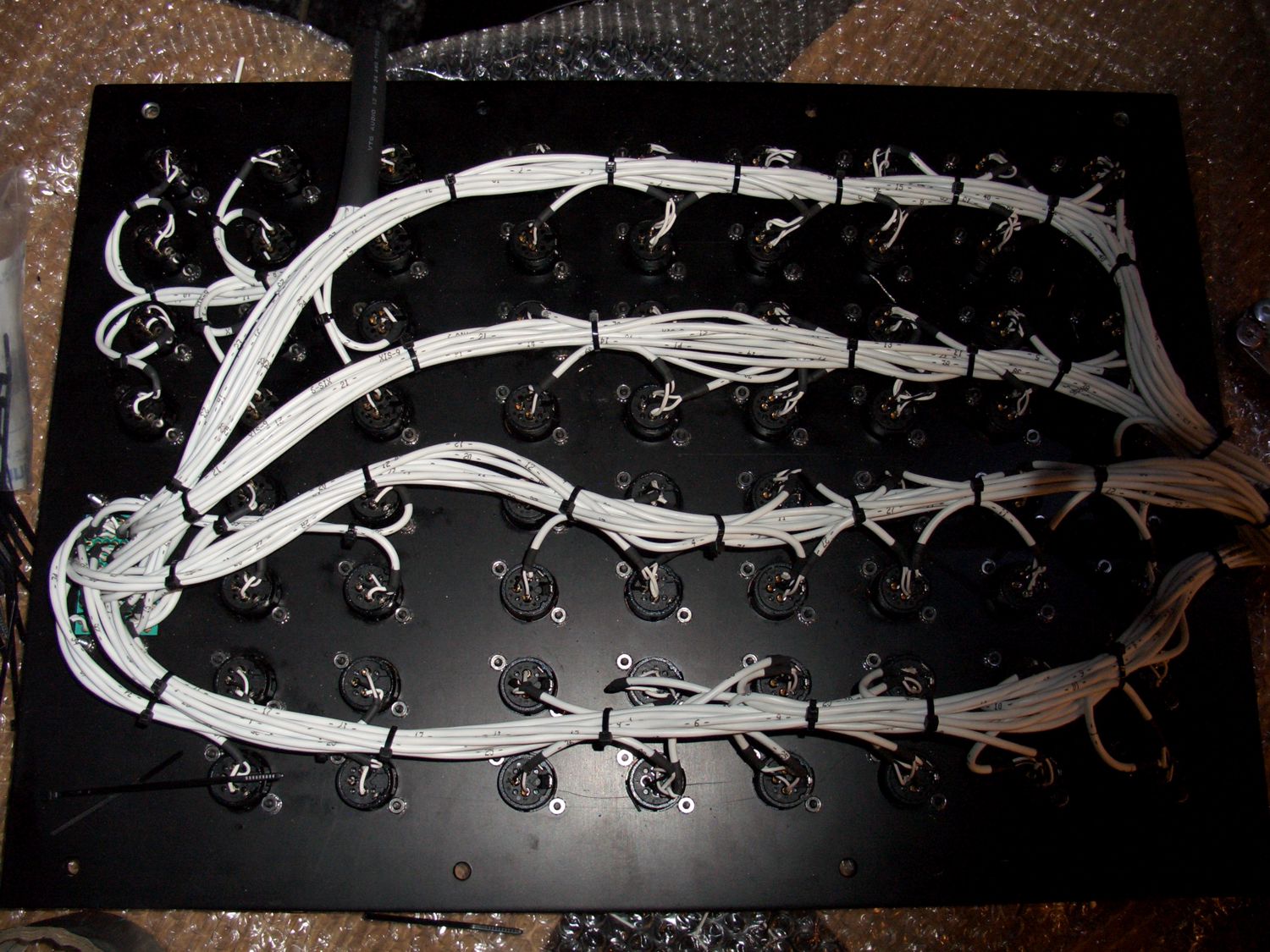
A considerable puzzle exists when figuring out the appropriate lengths and directions that the individual signal cables must travel in order to create a clean and serviceable set of connections to the mounted connectors. |
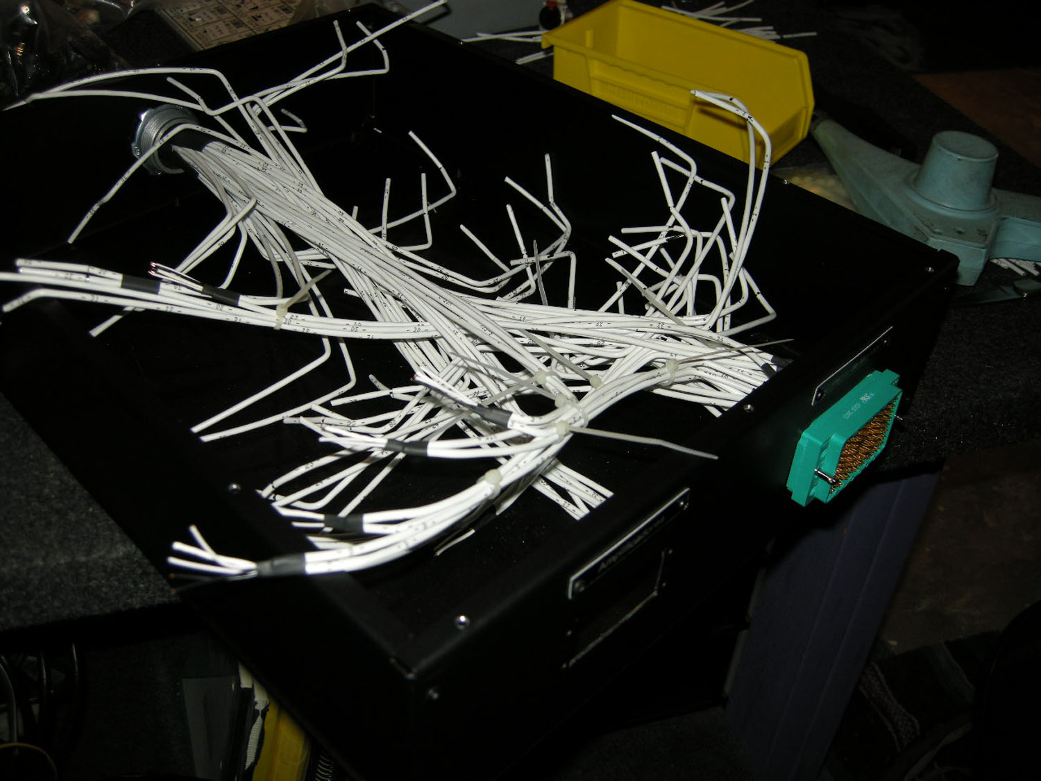
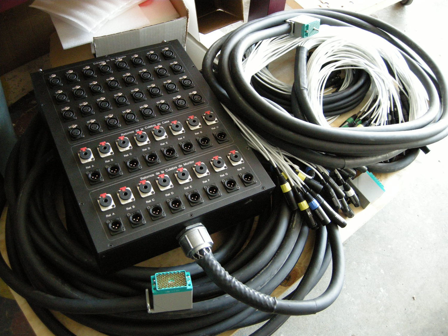
Shown here is the multipin split added to the main snake cable which in turn, can create a much bigger puzzle if not implemented with a reasonable amount of forethought on the layout of the individual signal cables. |
 |
 |
All of the internal snake head boxes are complete and the box is ready to be tested for signal continuity and integrity before being given to the client for use. |
The completed snake system is shown here with the attached snake head with multipin splits. The main and monitor feed ends have the audio connectors installed and ready for use. |
|
One of the latest audio wiring and system configuration requests we received was for a large local dance club. They anticipated having weekly musical acts and required an integrated and easy to use wiring system that would accommodate their vast collection of equipment they had purchased for the sound system. We designed and installed the wiring and interface panels necessary to hookup and route the band’s audio signals from the stage, out to the audio mixing board location and back to the booth where the amplifiers for the speakers are located. The project entailed about 200 meters of multi-channel audio wiring, a custom stage interface panel to allow the users to flexibly route audio to any number of scenarios they may encounter, and numerous terminations to various pieces of outboard equipment. |
|
 |
 |
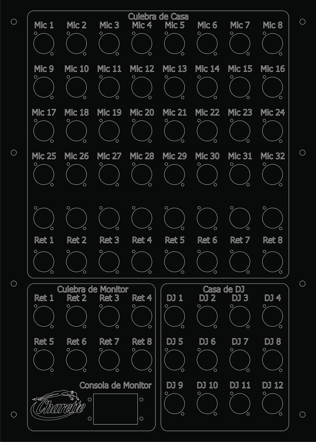
A view of the initial CAD drawing of the stage panel which contains sections for each of the locations that audio equipment is located in the PA system allowing for a single location with which to be able to easily patch between areas. |
A view of the wiring on the main stage panel. Microphones from the bands on the stage plug into this panel where then the signals are routed to the audio mixer as well as a secondary location for a monitor mixer. |
 |
 |
A view of the completed wiring for the stage panel. The panel also interfaces to the house booth where the audio power amplifiers for the speaker system reside. |
A view of the completed and installed stage panel, mounted in position and ready to be used. |
|
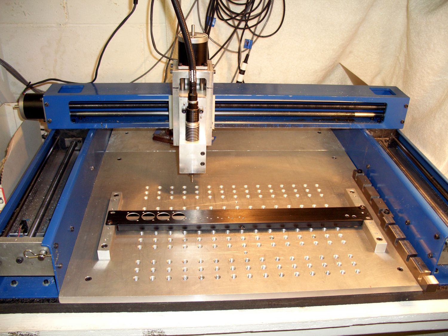
Quite often we have had requests to design and build wiring systems which require clear and easy to understand interface panels. We designed a CNC(Computer Numerical Control) machine that could accommodate the metallic panels that we need to machine for the designs in audio system installations. The unit takes our instruction from simple CAM(Computer Aided Manufacturing) software and allows us to engrave or machine any hole or design that is required into sheet metal or plastic panels. |
|
 |
 |
A view of the CNC work area. The panels for machining and engraving can be fastened securely into the base plate while the high speed router cuts the panel based upon direction from the machining program loaded into the software driving the CNC machine. |
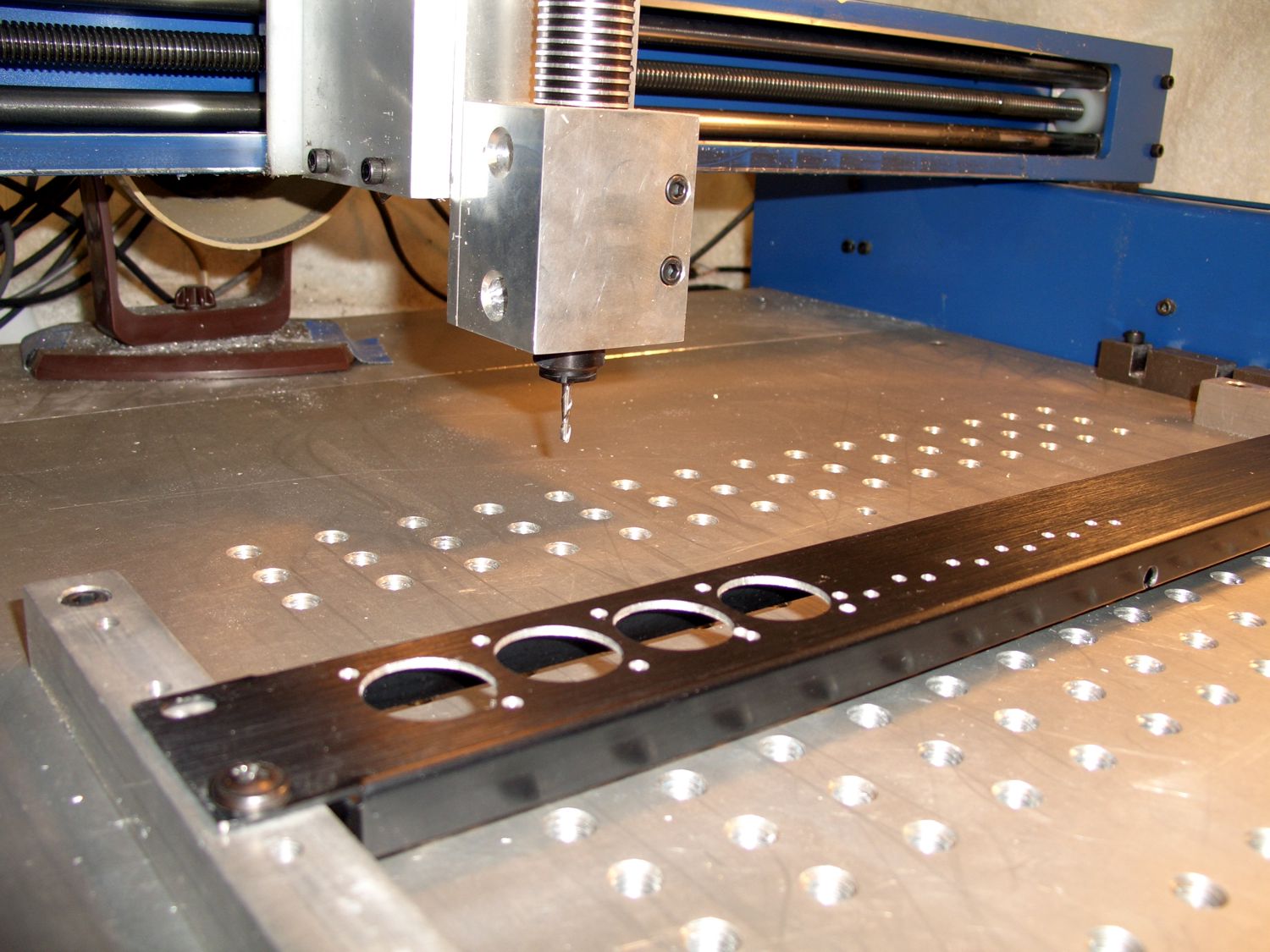
A closer view of the router cutter tip and a sample panel that’s been cut with some round holes for mounting interface connectors. |
|
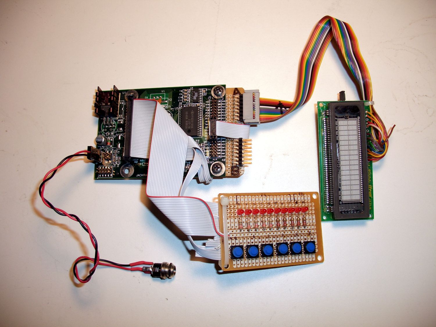
A recording studio that we frequently work with had requested a small hand-held device that could be used to store various equipment’s standardized memories via MIDI. We designed and built the architecture and programming for a small handheld, battery operated unit which would be easy to use and robust in function to accomplish many tasks in the MIDI domain along with storing and playing back memories. |
|
 |
 |
A view of the MIDI Recorder/Monitor prototype complete with pushbuttons, VFD display and indicator LEDs |
|
|
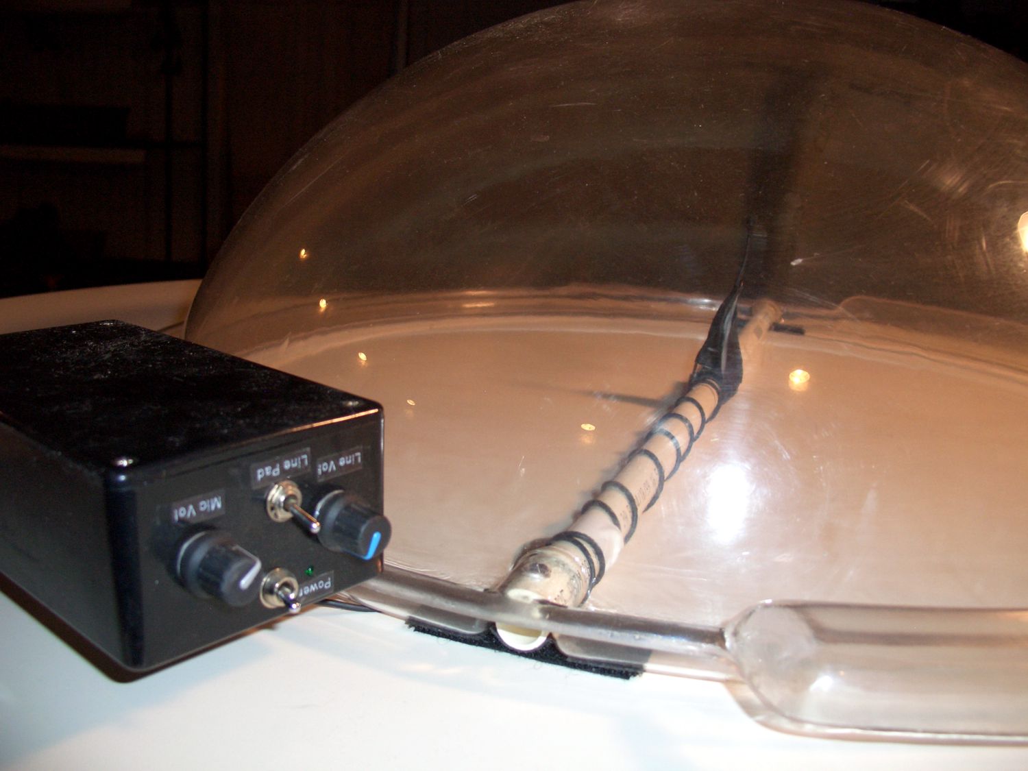
A colleague had approached me to assist with the design of a battery operated microphone preamplifier with an integrated headphone amplifier to operate a type of microphone he developed called a Para-Bowl parabolic microphone. It’s a large parabolic dish which reflects audio sound waves to a focal point above the dish which is then picked up by a microphone and electrically amplified to be fed into a set of headphones as well as drive a long length of cable for delivering the signal to the audio mixing location. The unit was designed for use at sporting events to enable sideline audio recordings of events taking place great distances away on the field of play. |
|
 |
|
A view of the clear plastic Para-Bowl parabolic microphone with the mic preamp/headphone driver and line amp attached to the side. |
|
|
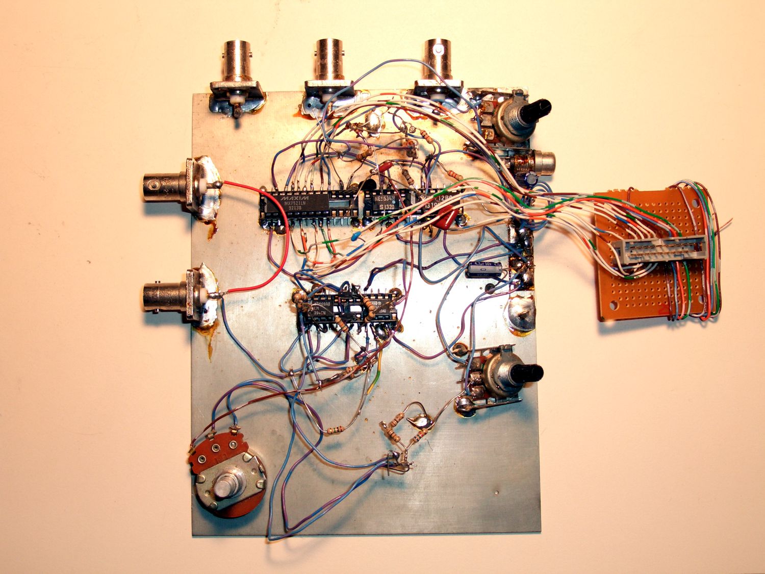
As an experiment several years ago, I wanted to see if it was possible to utilize a D/A (Digital to Analog) converter as a control element in an analog closed loop to generate a truly analog sine wave and control that sine wave’s frequency from a single command from a microprocessor. The result was a relatively simple circuit implemented with a multiplying DAC, some op-amps and a handful of passive components. |
|
 |
|
Here is the initial circuit prototype of the digitally controlled analog sine wave oscillator. It interfaces to a regular parallel printer port to assign a current “weight” to the multiplying D/A converter. |
Believe me, this circuit does in fact work. I should have a nice pic of a scope trace in the above window showing the beast in action. If I have some time, I'll dig it out, see if it still does its sine thing and snap a pic for here. |
|
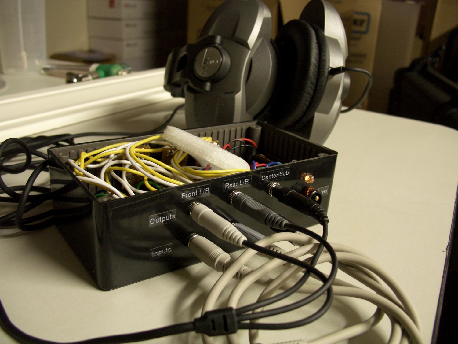
A client had the necessity to perform a demonstration of some multichannel surround sound material through some custom surround sound headphones. They needed to be able to drive six channels of analog audio and be able to control the volume and have sufficient current to drive the headphones. We designed a small prototype headphone amplifier to accomplish the task. It's equipped with three TRS mini jacks for inputs and three TRS mini jacks for outputs. The volumes are controlled with stereo pots in pairs, Front L/R, Rear L/R and Center/Sub. |
|
 |
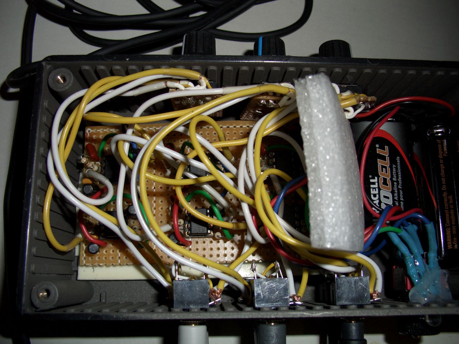 |
A view of the six channel headphone amplifier and the custom surround sound headphones in the background. |
A closer view of the inside of the six channel headphone amplifier with its PC board and internal wiring. Sometimes, prototype circuits take on the look of a pile of spaghetti. |